Nerf gun turret

I was working on a Nerf gun turret in my previous employment at a special needs school but never had time to finish it. There are a lot of very disabled children who don’t get to run around and wrestle like other kids do so I was trying to think of a way of them getting in on the ‘boisterous play’. The Nerf gun turret was meant to be something they could use with a small thumb joystick similar to one used to drive an electric wheelchair, or even controlled with eye gaze tracking. For this iteration I just hooked it up to a USB gamer joystick.

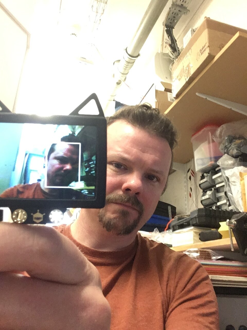
There are definitely some improvements to be made, the rig is flimsy, the tilt servo could do with some gearing, the gun often jams and I may have smoothed the input a little too much, but we are getting there! I’d love to hook it up to the Husky Lens and get some AI image tracking going on… face recognition to only attack a certain person?

Raspberry Pi Portable Power & Safe Shutdown

So I have been building a few portable things with Raspberry Pi Zero lately and I’ve been using the Adafruit PowerBoost board. Its a great board for bumping a 3.7V LiPo battery output up to 5.2V for running Raspberry Pi projects, plus it handles charging, has low battery detection and you can turn off the output with a pin. The only problem was being able to do a safe shutdown and then use a pin from the Pi to cut the power. I’m kind of surprised there isn’t a board and prebuilt solution for this and it took a lot of research before I came across NeonHorizons LipoPi repository. The functionality I was after was in the Power Up/ Power Down version and I used the ‘Simple Press’ section as the basis of my circuit. I was using the Adafruit Speaker Bonnet for my project so I could not use the suggested pin 18 and changed it to 27, but the rest stayed the same. Anyway, I put the suggested circuit onto some strip board and the solution worked perfectly so kudos and thanks to Daniel Bull. Check out the repo for the code, instructions and circuit diagrams, my circuit is below.

onOff button and powerboost.png


Huskylens Easy-to-use AI Vision Sensor


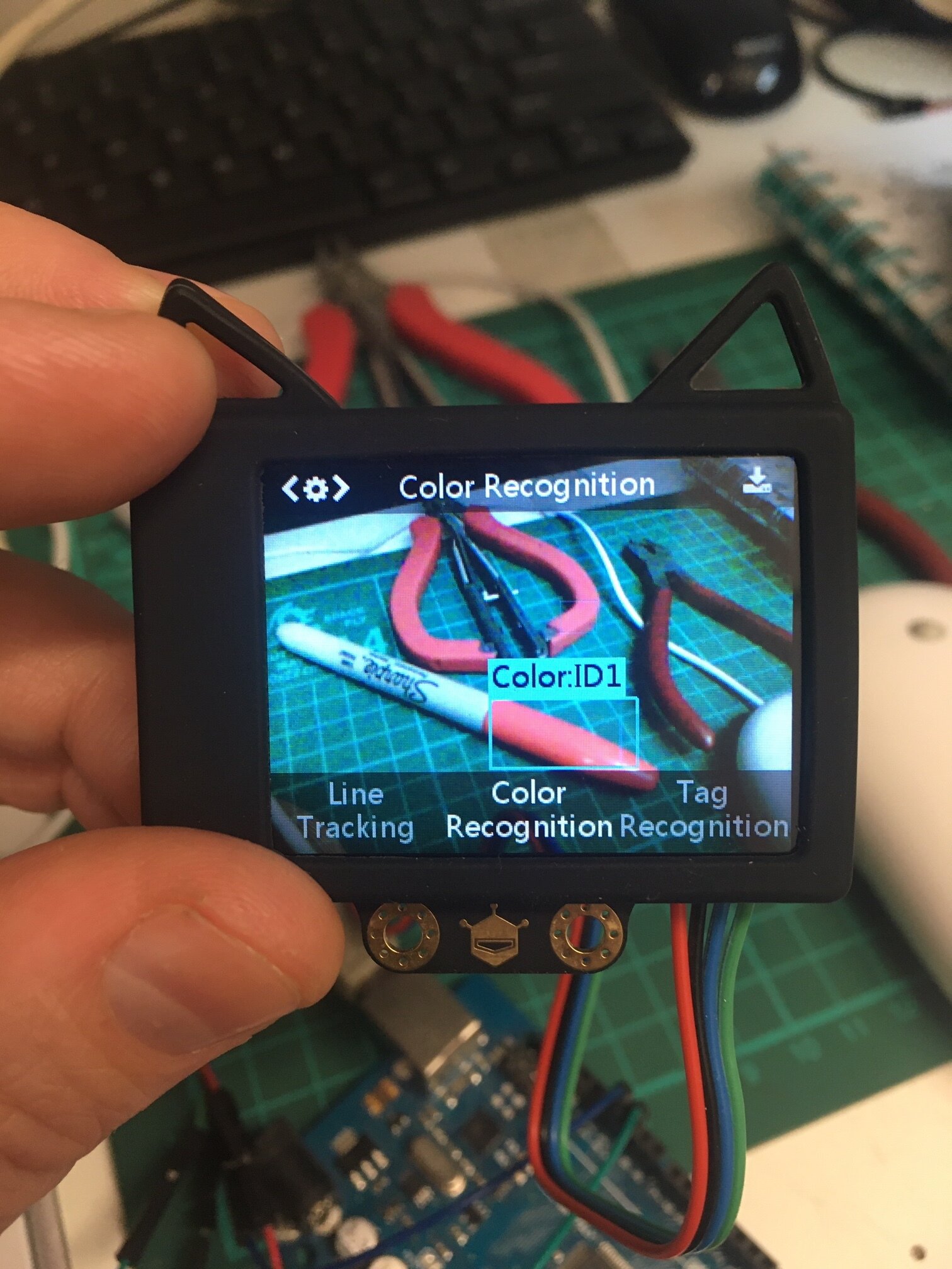
I just received my DFRobot Huskylens having funded the Kickstarter a while back. Of course there is zero documentation at the moment, I couldn’t find anything much online and was having trouble reading serial from the device. In the end I searched on Github and found an Arduino library. If you download the zip, unzip it and then rezip the ‘HUSKYLENS’ folder inside the main folder then you can import it as a zip library as described here and then access the examples.

I had a quick play with the device and managed to get location data coming in to my Arduino for tracked objects and it seems pretty simple to learn new ones. Now if I can hook up some face detection to the nerf gun turret I am building we can have some fun…

Smart Film

Well, the Shutter Glass was super cool, but I can’t seem to find it in big pieces and you need to use power to hold it dark . Smart Film is frosted and then you apply power to clear it which is more what I am after, again, cool stuff!


Paper craft electronics birthday card

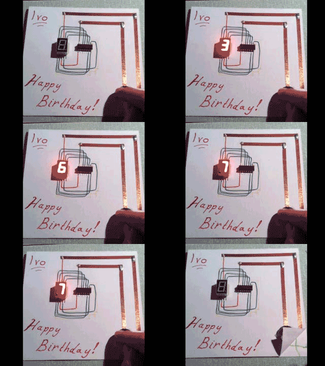
It is my sons 7th birthday today and it has become a tradition to do a paper craft electronics card for him. These have tended to get a bit more complicated every year so there is a warning there to start simple! This one uses an ATtiny 84 chip programmed via an Arduino to run a seven segment display from a 3V button cell. I used very thin kynar wire and copper tape for the connections to make it count up to and flash his age. Definitely one to do before they reach double figures!! 

It would be great to print the circuit outline onto the card to scale and do some nice design on the computer, my drawing (and writing!) skills are somewhat lacking! 

Softpot

I got one of these 'Softpot' membrane potentiometers recently as a way of telling where a finger is pressing on a strip. I rigged it up like a normal pot and it worked but was pretty noisy, I put a capacitor over a couple of the pins and it seemed to help a lot. Then I read that if you press at the top and bottom you can create a short circuit and it gets hot, so I had to try it... It did indeed get exceptionally hot very quickly and as I don't particularly want people to burn themselves or fry the strip (it's not cheap!) I tried adding some resistors. The more resistance you add the more resolution you lose so I settled on the circuit below which seemed to do what I want it to. Besides that, you can read it in Arduino like a normal pot (check the AnalogInput example), though there is a bit of 'floating' when you have taken your finger off that you have to deal with. 

A first look at the BBC micro:bit

We received some of these cute little ARM based boards aimed at helping teach STEM to Year 7 children. They are really easy to use with a variety of coding environments and are great fun, but can do some pretty serious stuff too. The ring pin outputs are good for croc clips, banana plugs and conductive thread and you can access the other pins with an external edge connector. 

image.jpg

It has an accelerometer, a compass and BLE and the coding environment has a great simulator for testing your programmes before you upload. 

image.jpg

I will report back when I have done some more playing...

Designing electronic instruments - 2

Following on from this post.

On Monday we met to discuss the first prototypes of the two instruments we wanted to explore as detailed in the previous post. 

The Filter Box

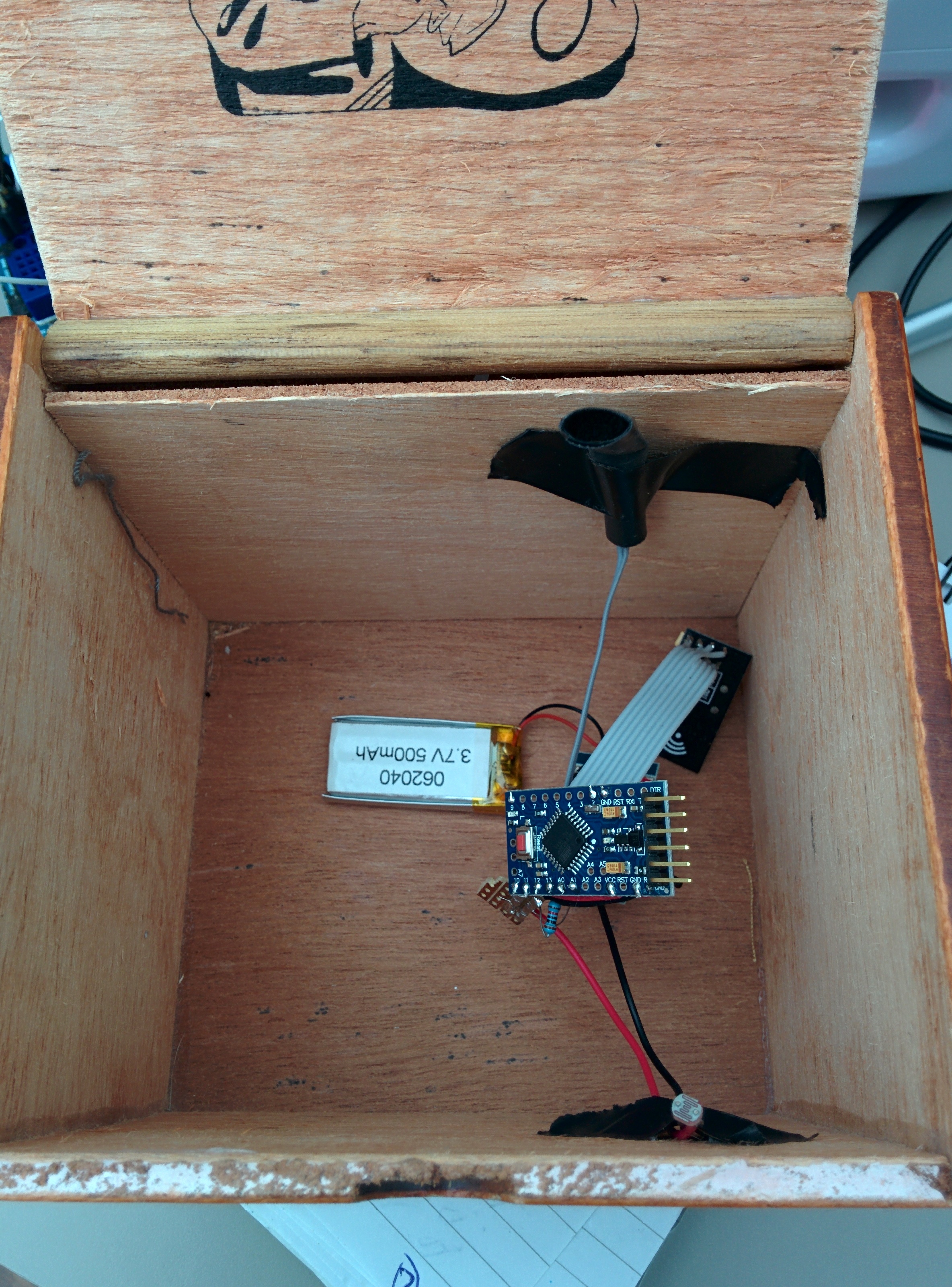
We took a look at the first Filter Box prototype as seen in the pictures below which was set-up in a temporary box for testing of the sensors. I bought several small wooden boxes to try for size, shape, and general ergonomic-ness when holding, and to enable discussions as to what might be good features and functionality to have in the box. 

Our idea was to create a wireless filter box. I wanted to use some of the nrf240l1 radio modules I have acquired as they provide a very cheap mechanism for wireless communication, and there are lots resources available to make them work with Arduino. A detailed tutorial on using Arduino + Nrf24l01 running into Max/MSP software can be found on my website here

Discussing the box!

We discussed:

The wooden boxes I had purchased and selected a small oval shaped one as the best shape and size to fit in the hand. 

Buttons- having some (x2) to enable more functionality- options included click buttons that would provide tactile feedback when depressed or valve style that would more naturally mimic an interaction with an instrument such as a trumpet, like a valve, these would give feedback not as obviously as a click but more suited the instrument paradigm. 

Adding a force sensitive resistor (FSR) that could then be pressed harder or softer to achieve some of the effects you would with other instruments such as when fretting a guitar, and allow expression through fingertip movement and pressure of the hand on the box. The mapping of the FSR could then be naturally connected to something like the amplitude of the sound so when pressed harder the sound would be louder, again going with what a player might naturally expect from an interaction of that style. 

Light dependent resistor (LDR) this worked well as a mechanism to control some sort of filter, or for example the mute of a trumpet, the cutoff frequency of the sound or the volume. This is taking the movement of the opening and connecting it to any kind of parameter that might need fine movement and can be used to get effects like vibrato and tremolo. A parallel can also be drawn between something like scratching (dj style) by opening and closing the lid, and when connected to a filter controlling some element of feedback, using noise as the sound generator. We had a little play with using the light dependent resistor to control the cutoff frequency on a filter over sounds and using the motion to trigger MIDI notes but felt that the latter did not really play into the strengths of the opening and closing of the box as much as the controlling of an effect. 

The aim with the filter box was to create something that when held in a natural position would allow access to the 2 buttons and the FSR as well as facilitating the opening and closing of the lid so that the elements could be used in conjunction with each other and separately in an ergonomic way. 

The Pressure Box

We discussed the pressure box and using an array of piezos arranged around the bottom of the circular wooden box to create 8 potential pressure points. The Arduino pro mini we are using in the instruments allows for 8 analogue inputs so would suit this set-up. The box can then be filled with foam and topped with a soft tactile yet spongy material such as neoprene, or potentially some sort of skin stretched over the top in the style of a tambourine and secured down with pins. Being that the piezos are very sensitive to vibration there may be some cross talk between the 8 units but this could provide useful for expression. The sensitivity of the piezos allows for tapping the box to trigger or modulate the sound also. 

Future boxes

The hexagonal box though not used yet could potentially feature a new mode of interaction for each of its faces to allow a player to choose their preferred interaction mode and mechanism, this may be one for future exploration.

Next Steps

I will now review what we have discussed and implement them into some more prototypes! 

Vibrotactile Loop - Threeways School, Bath

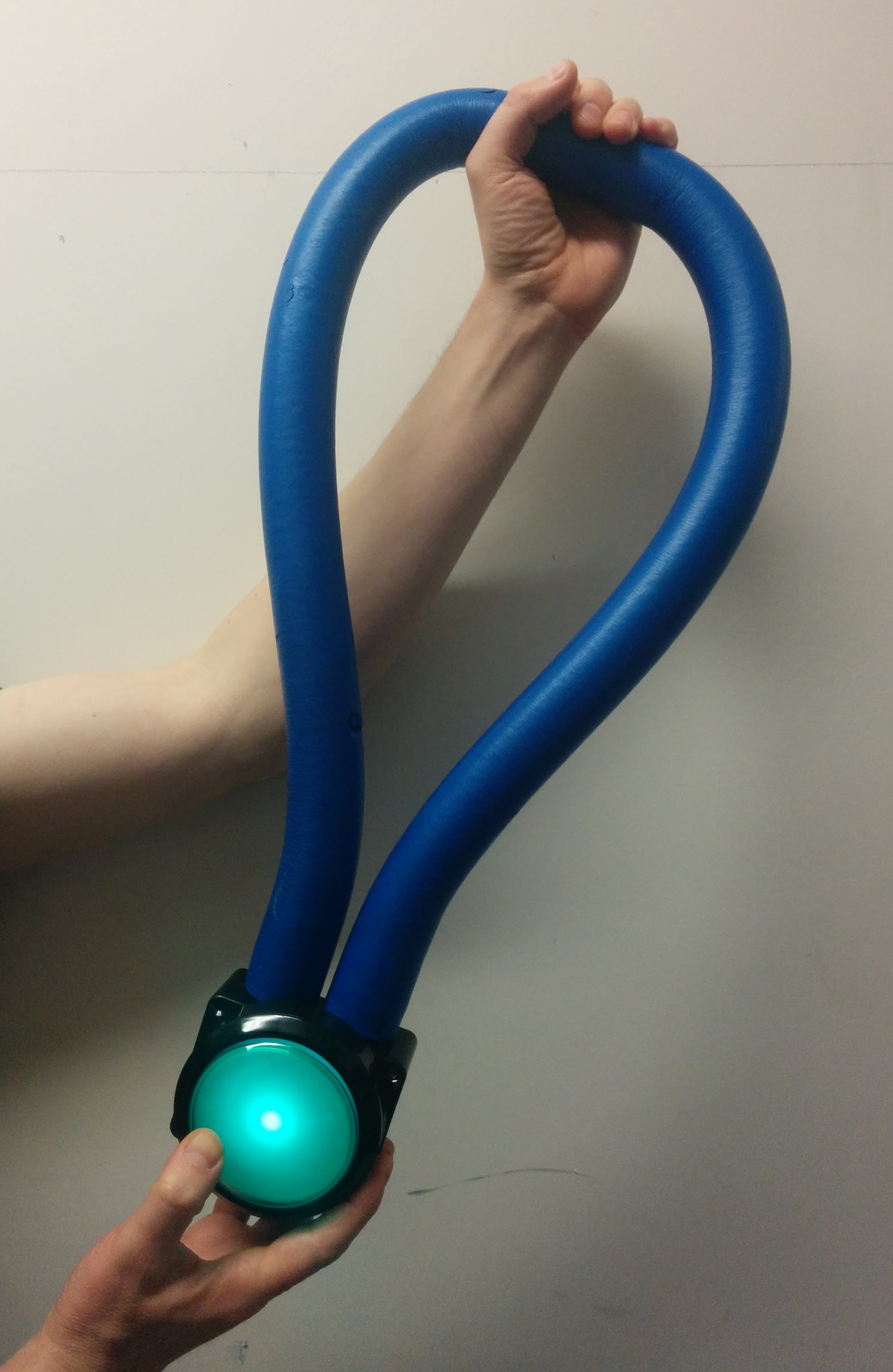
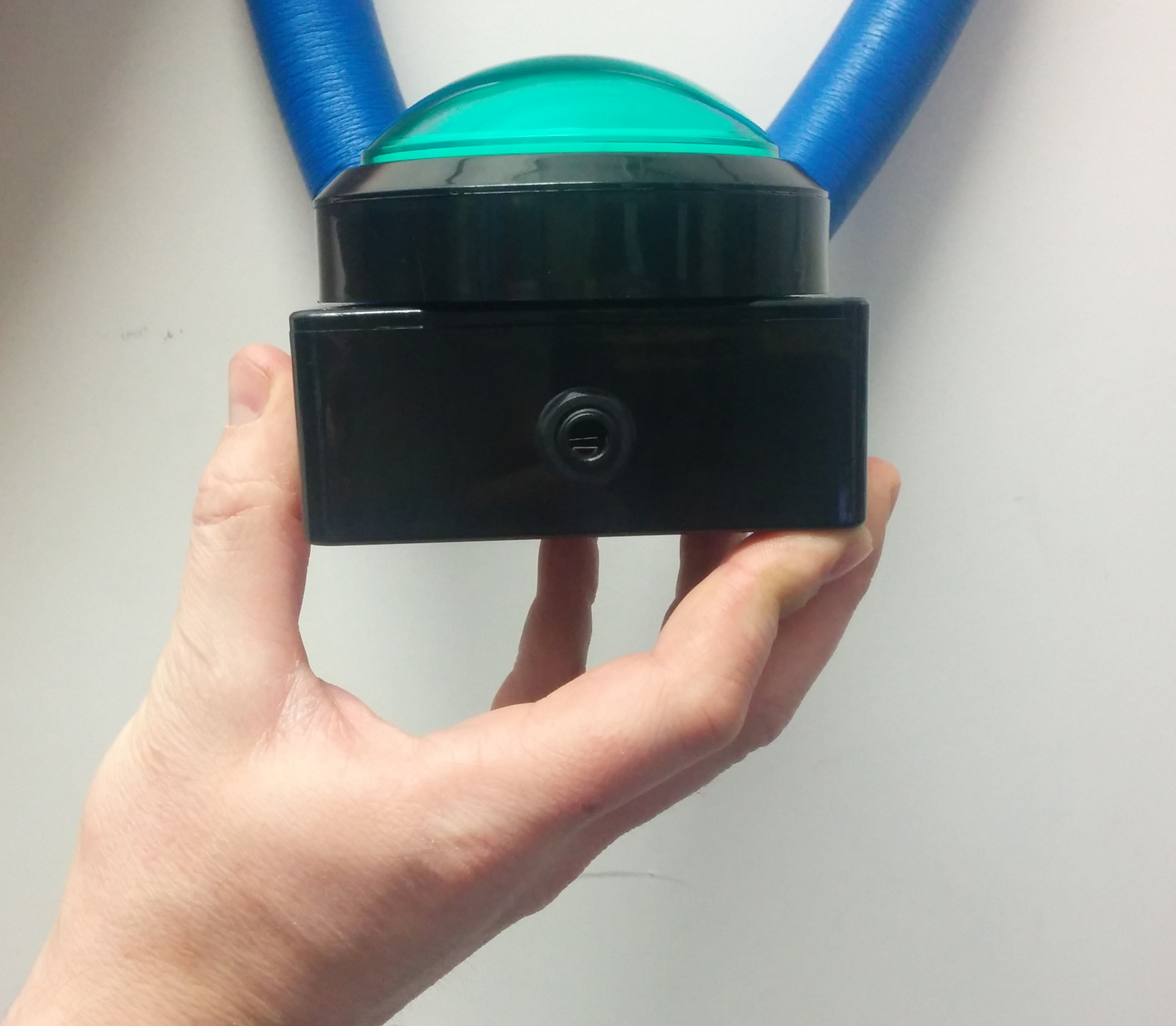
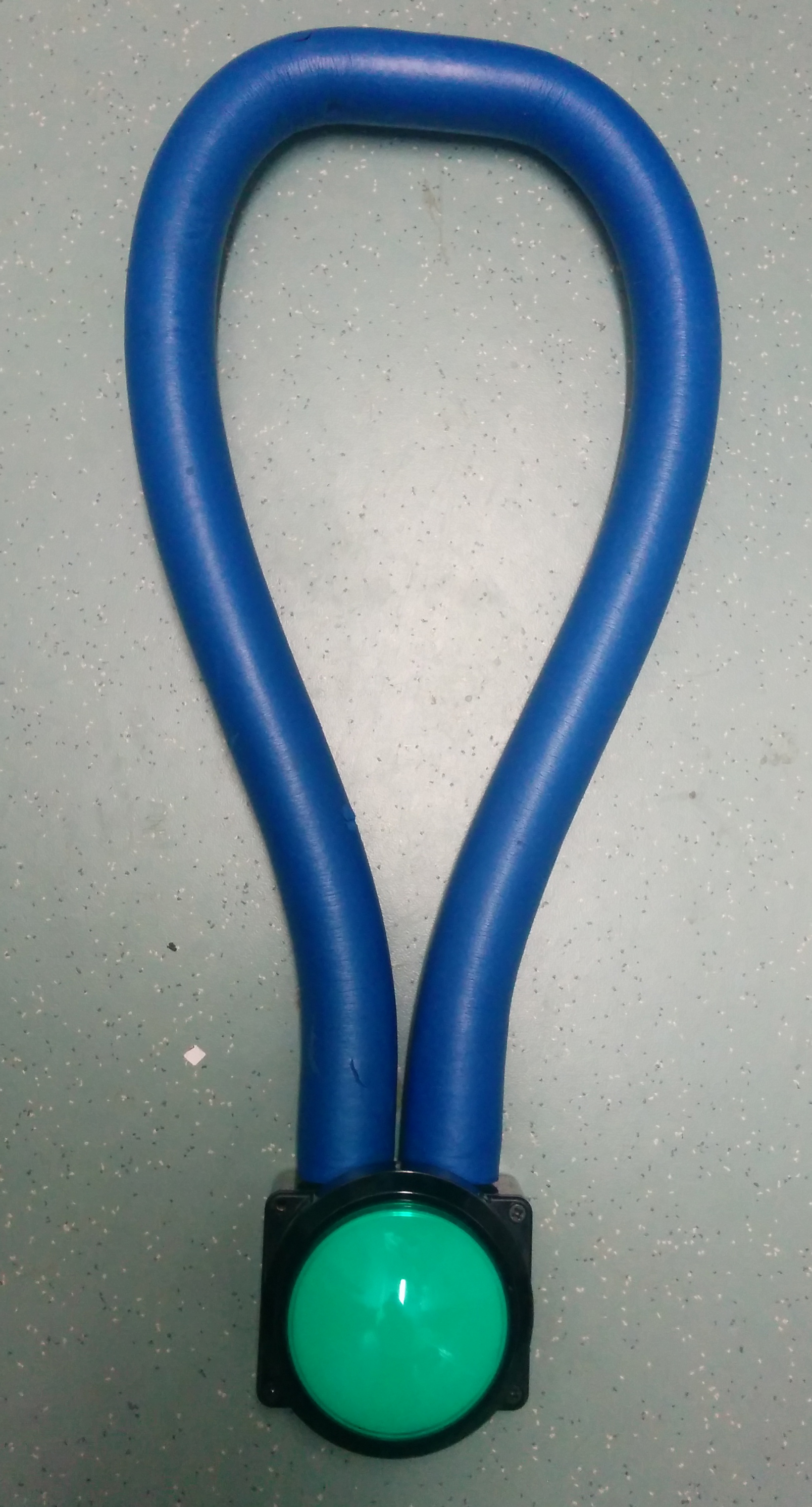
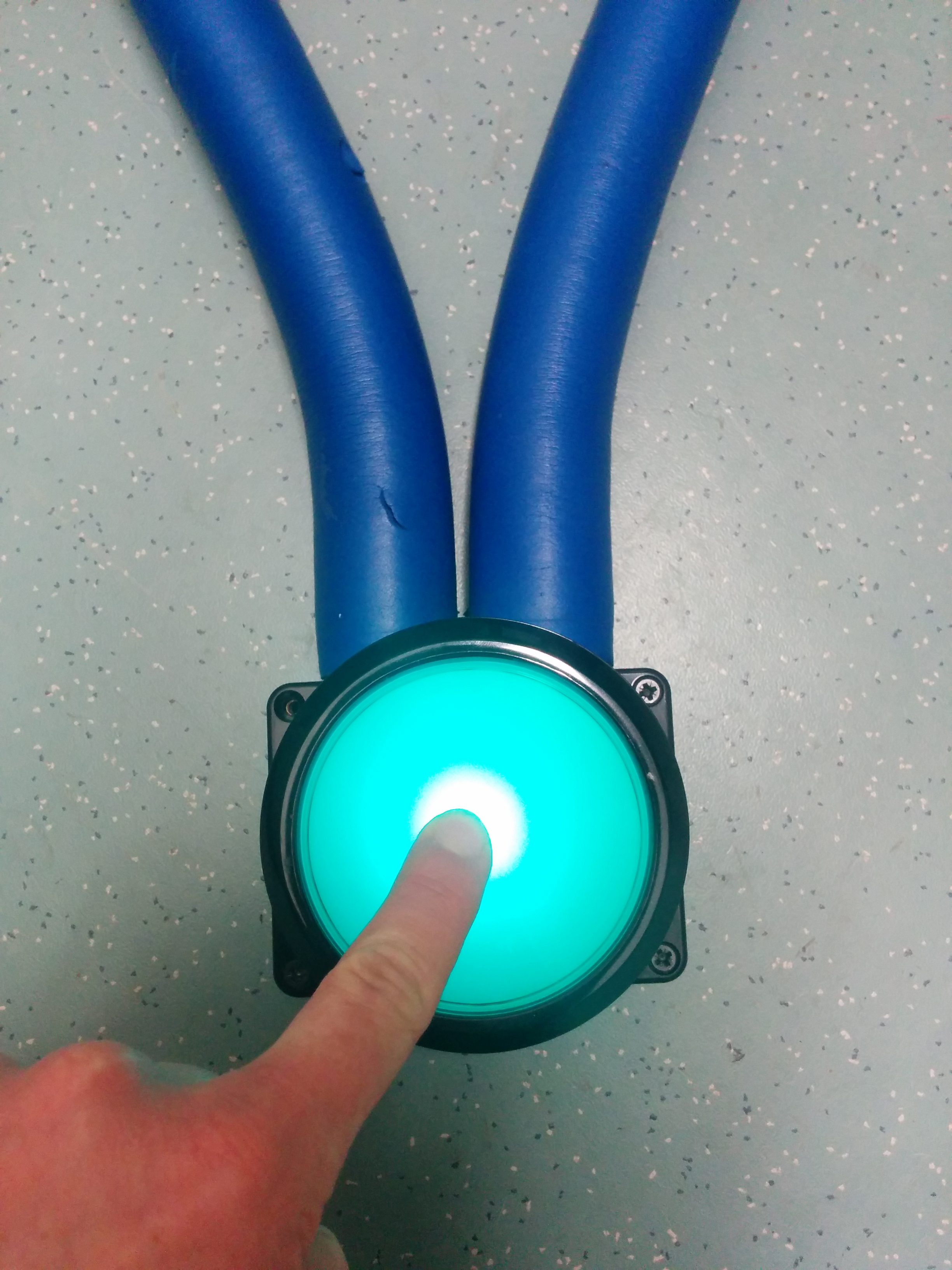
At Threeways we made a vibrotactile loop that can be activated using an on-board switch or an external switch plugged in through a Jack port in the device. Pressing the button to activates the vibration which is provided by a motor housed in a synthetic rubber and PVC repurposed from a massage tube. We had this tube spare after using the caps from it to fix 2 other massage tubes and thought it would be a shame to waste it, so the vibrotactile loop was born. This packs quite a punch and is a great tactile sensory tool. 

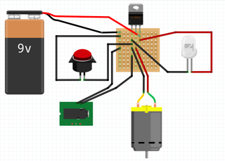
The last image in the grid above is the Fritzing plan for the simple electronic set-up inside the main box. The components we used were: 

Cool components big button. LED that came with the button. A 1/4 inch audio socket. A 3v regulator. A 9V battery clip with 9V battery, some wire and a piece of strip-board to connect it all up.

When using the 3v regulator be careful to check which pins are which before connecting. The motor requires 3v and the LED 12v so we used, as an in-between, a 9v battery with a regulator to allow 3v to go to the motor and the 9v to go straight to the LED.