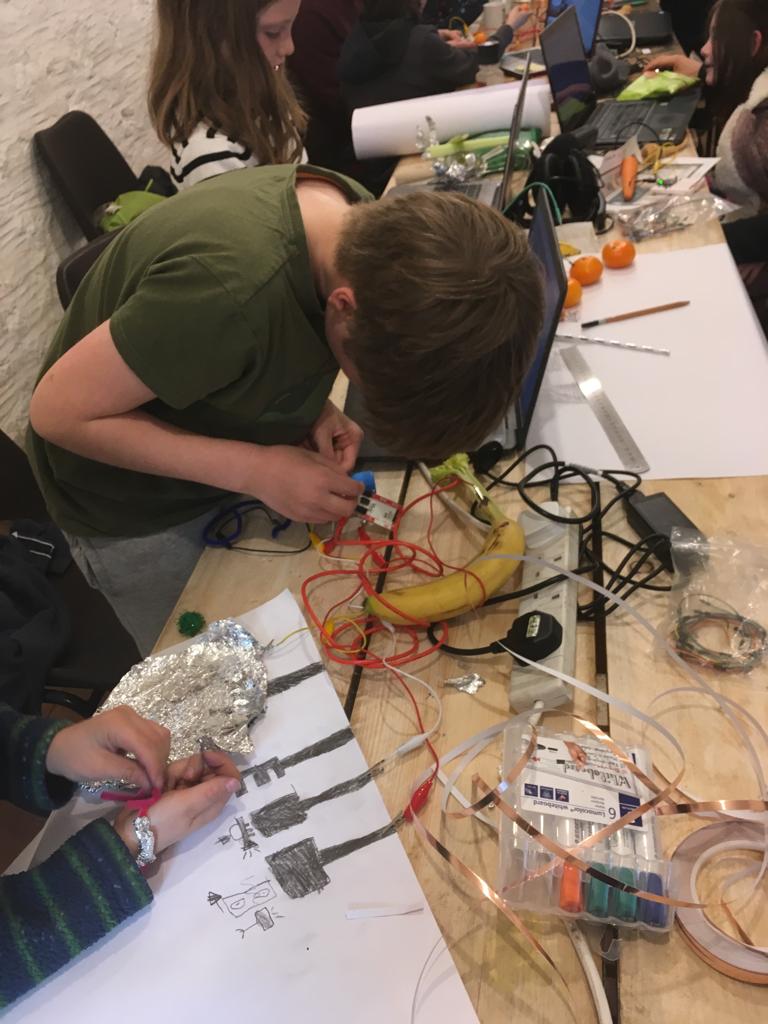
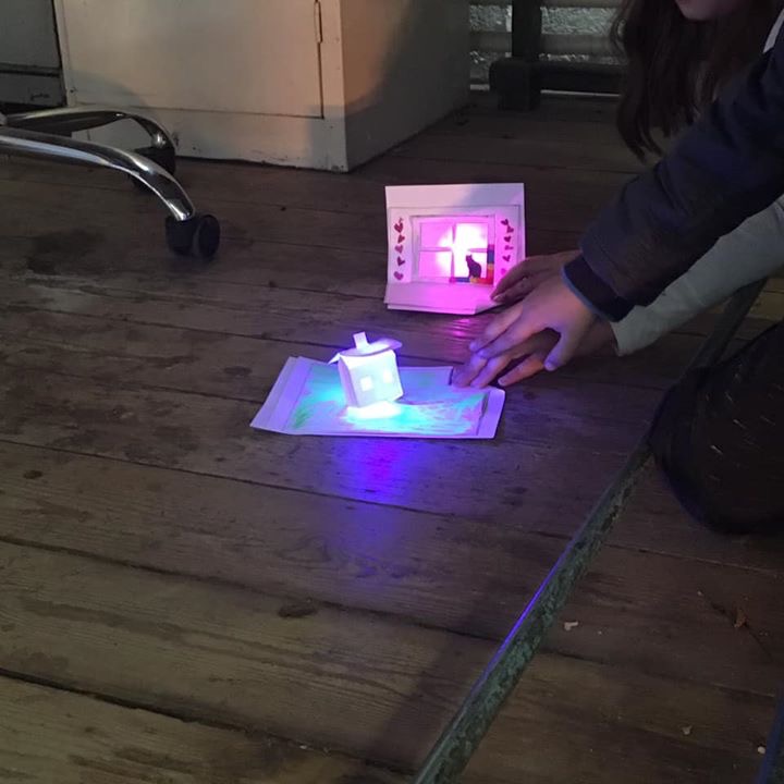
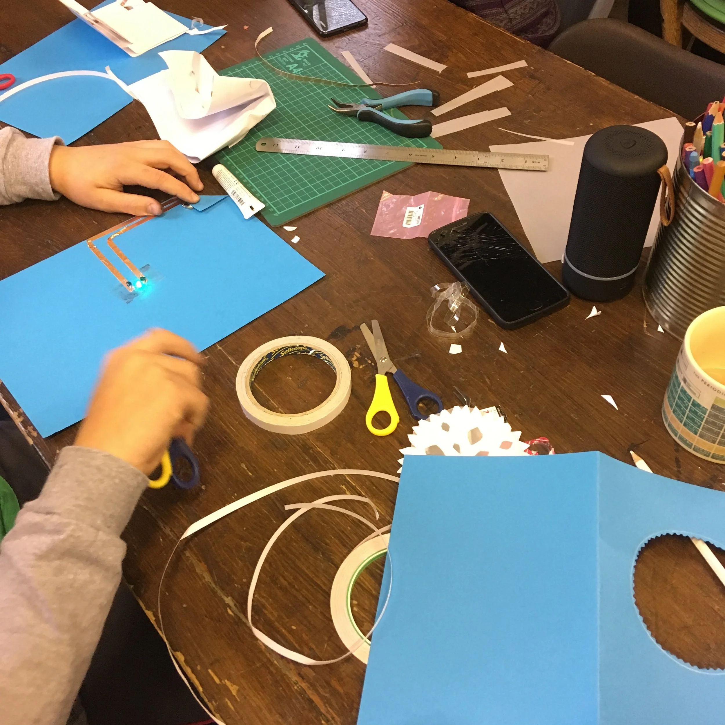
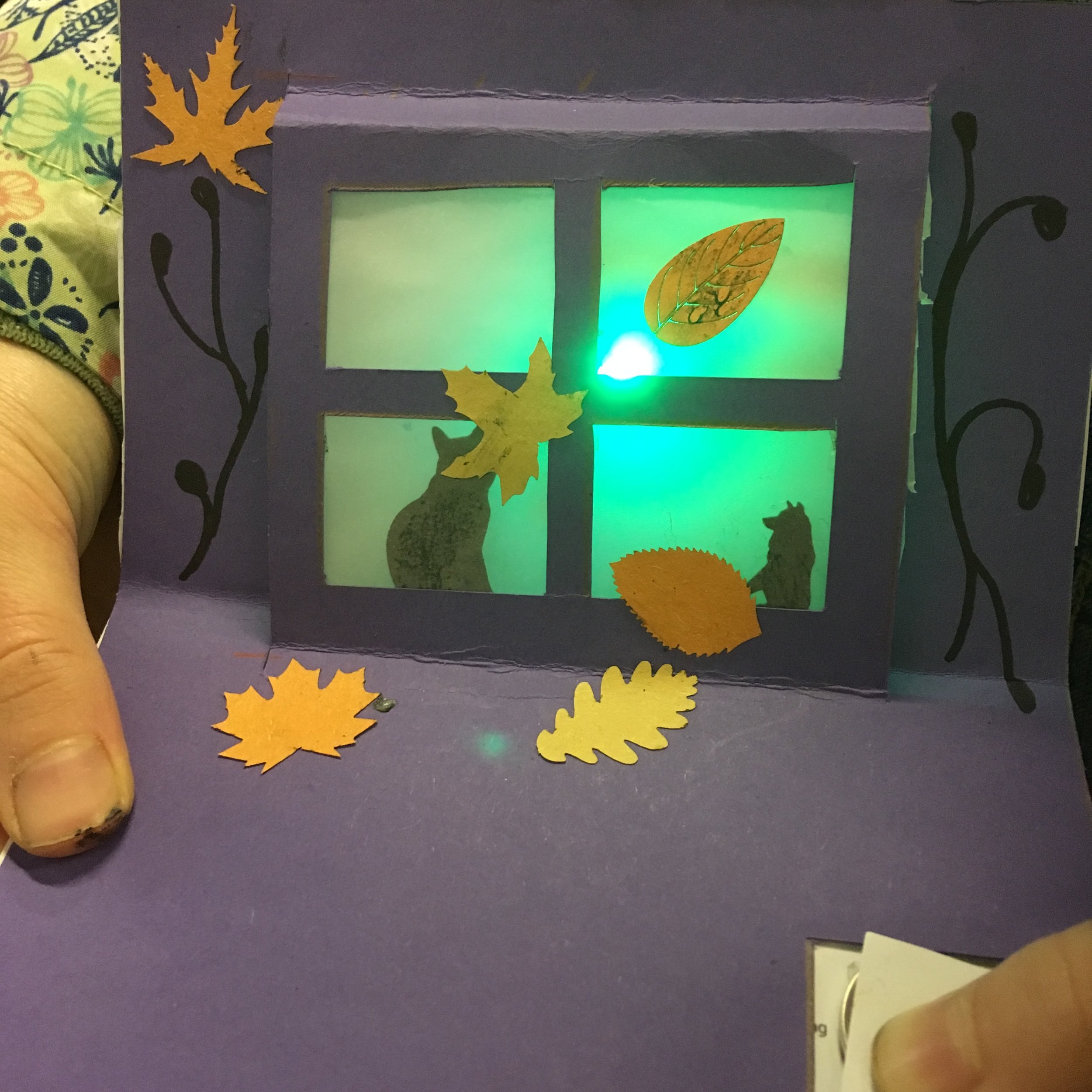
I recently did some STEAM (Science Technology Engineering Art Maths) workshops at Edventure in Frome. We explored paper circuits, programming in Scratch and making interfaces using the Makey Makey. I had lots of fun and the feedback was great, there were some impressive creations!


Feather Huzzah32 - ESP32 OSC

I was a fan of the old Huzzah board based on the ESP8266 chip, but it only had one analog input which made it unsuitable for some projects. The new ESP32 chip has loads of analog inputs, bluetooth/BLE and is pretty packed with GPIO and features! Check it out here at Adafruit.
I have been using it to send button and fader/sensor readings over WiFi using OSC to my computer running Max MSP, it is a great tool. I have created a repository here with all the coding and information to set it up.
Interactive floor projection
At Three Ways School we recently purchased an Optoma ML750ST projector for dedicated floor projection. This is an awesome little projector, it is tiny, has a short throw lens and an LED light source. I'm using it with an overhead IR camera to do some interactive floor projection which I programmed in Max MSP. Check the video:
Wifi RFID sender
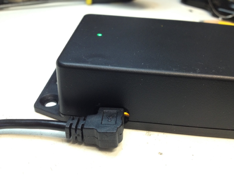
I have been putting together an RFID reader that can send tag IDs over Wifi to a machine running Max MSP on the same network. I have used an RC522 reader which I have blogged about before, and the recent Adafruit Feather Huzzah board which is based on the ESP8266 chip and includes an onboard Lipo charger so is great for portable IoT projects. For once I managed to find an enclosure of pretty much exactly the right dimensions, it was tight but I crammed it in including switch and indicator LED. The hardware will be used for a project at Three Ways School that aims to give non/pre verbal children a voice, more details to follow...


Arduino / Xbee network
I will be running some workshops on the Creative Computing course at Bath Spa in January with kit supplied by Farnell Element14. I want the students to create a network of nodes that communicate with each other and have some element of generative algorithm to them. I have built a proof of concept as seen in the video, a single node generates an audio and LED output and sends the message to another node, that node displays the incoming message and then generates one of its own to signal another unit. Right now everything is generated pretty randomly and the nodes choose another one to send their message to at random. Things will get more interesting when we link colour and audio frequency and think of more interesting ways to generate our message. Perhaps some nodes will favour talking to others or malcontents will start interrupting the current conversation? I am interested to see what behaviour might emerge when there are 10 of these things going and each has its own 'personality'...
Delivery!
Exciting box of goodies just arrived for a collaborative project in January. I will be working with Bath Spa University Creative Computing course and Farnell Element14 to create an Internet of Things workshop.

RFID RC522 + Huzzah ESP8266
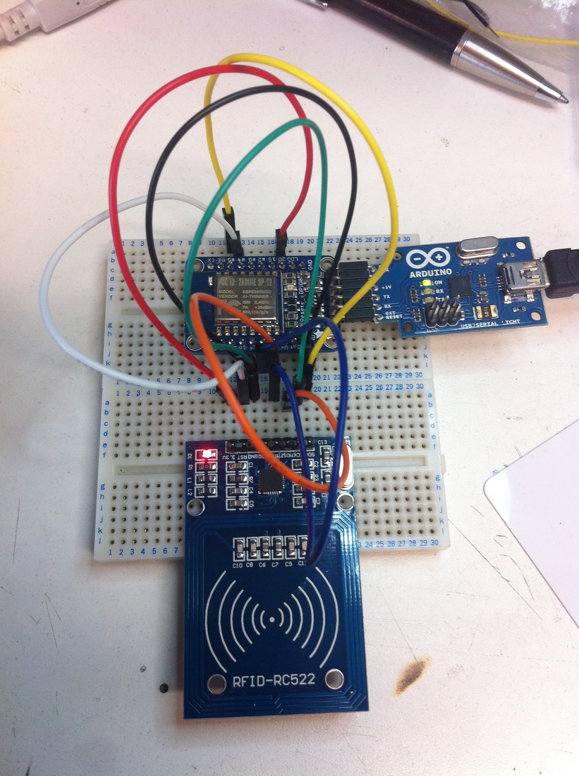
This revisits the RC522 RFID reader that we blogged about here. I wanted to be able to use it with a Wifi connection to ping RFID tag IDs over the ether so I started hooking it up to a Huzzah ESP8266 board I had and after a bit of fiddling it worked! Its only sending over serial right now, but if I can get it going over Wifi, this is an incredibly cheap RFID tag beamer. The new sketch with a description of the pin connections can be found here.
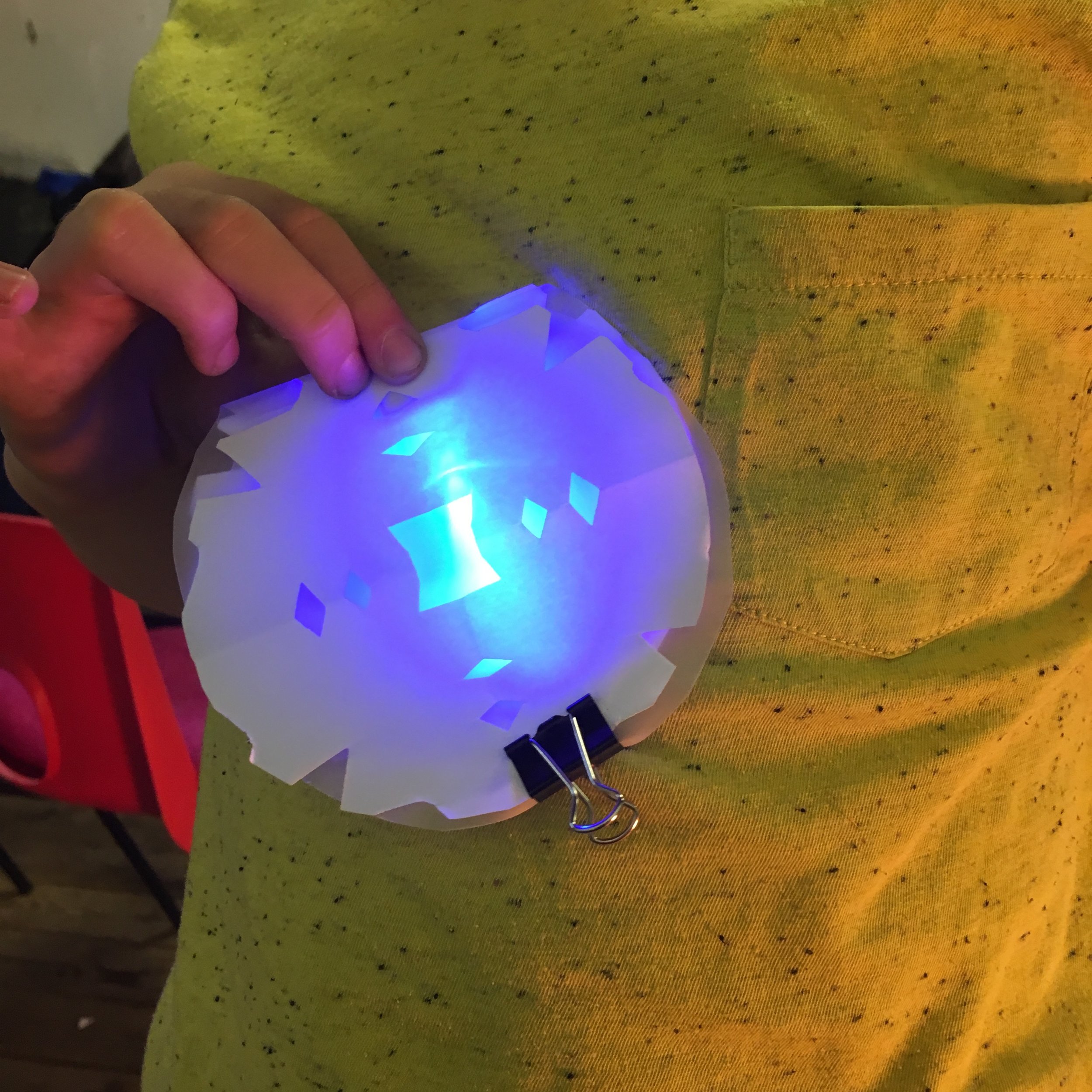
Cloud lamp

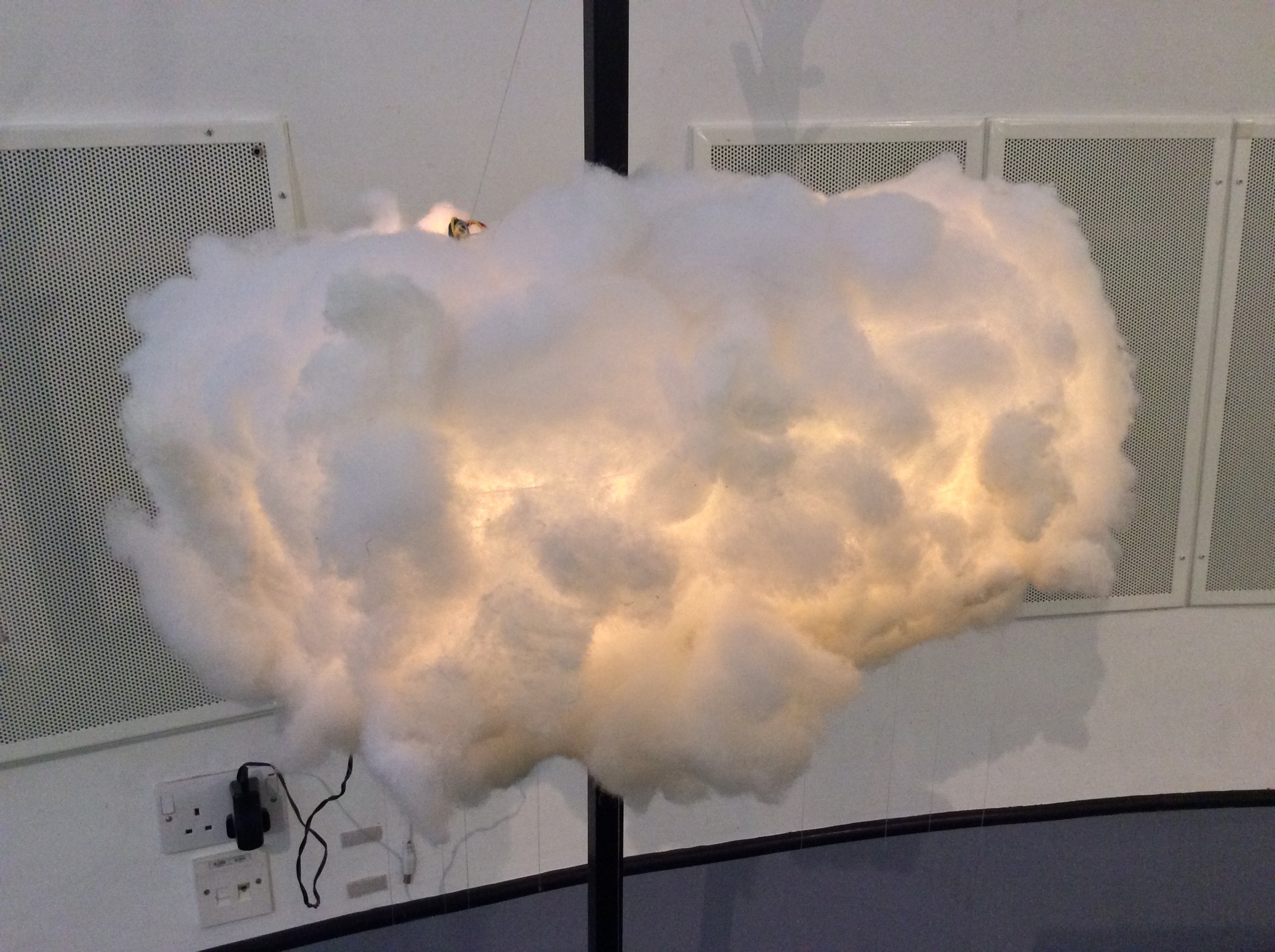
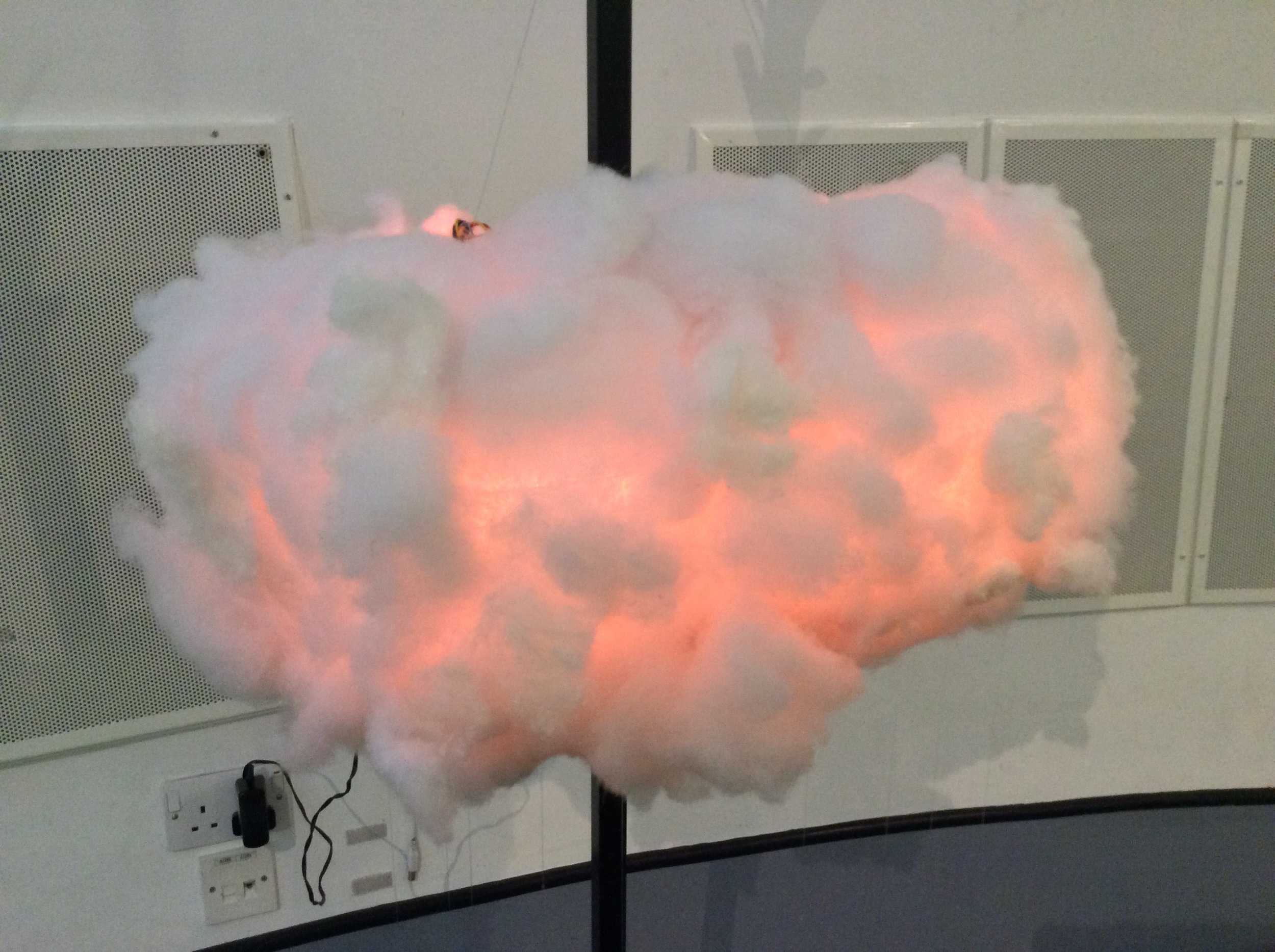
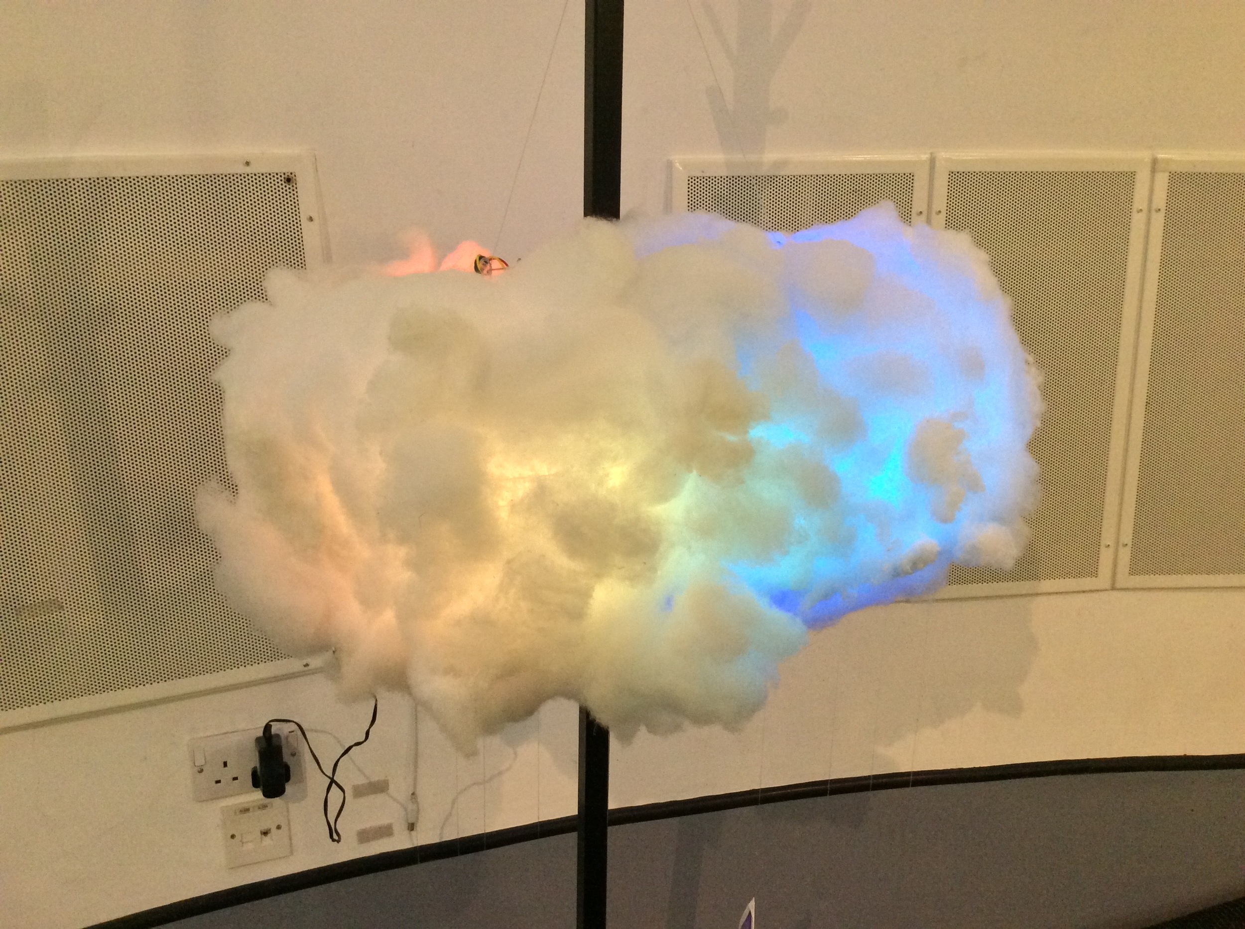
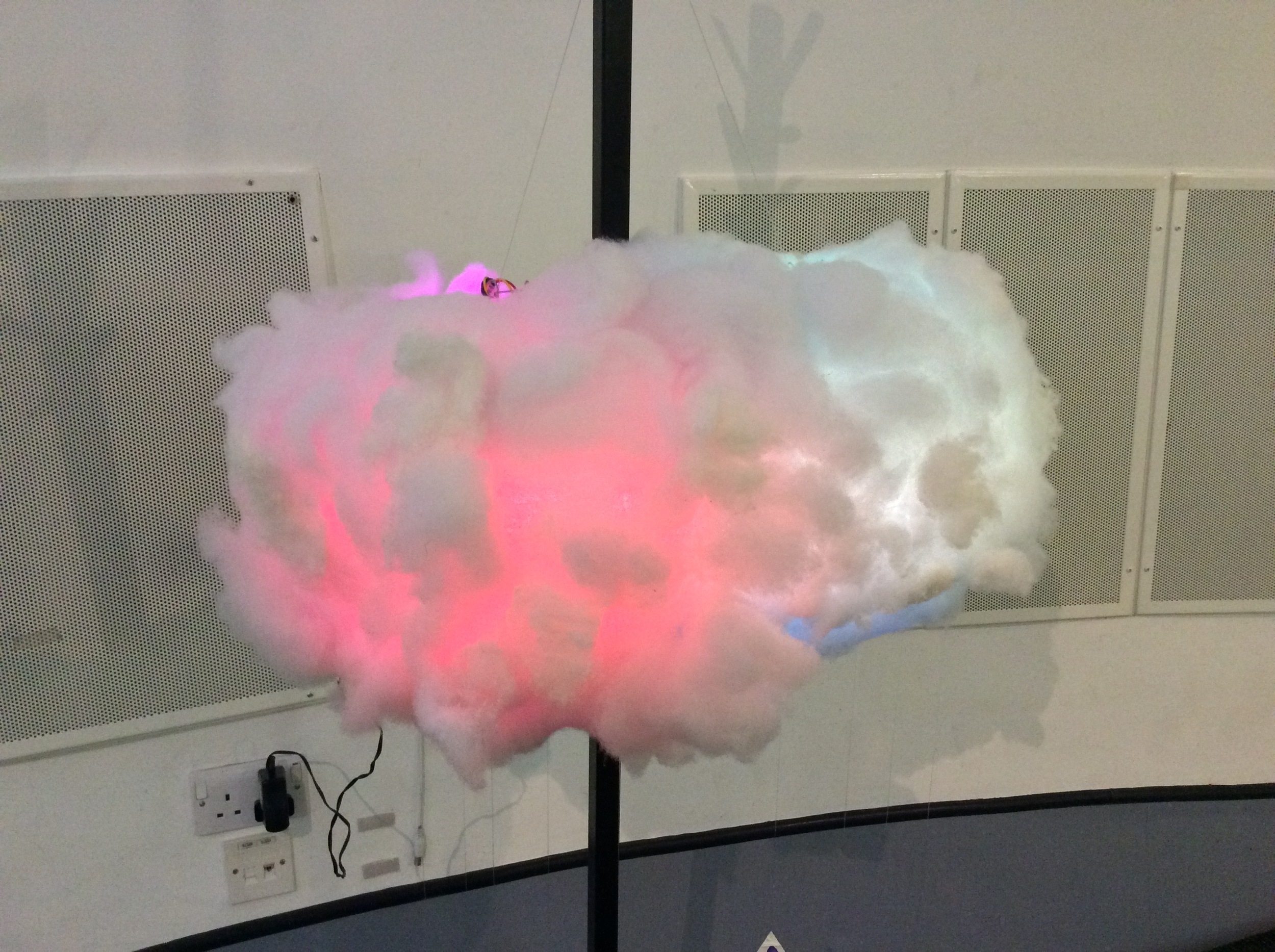
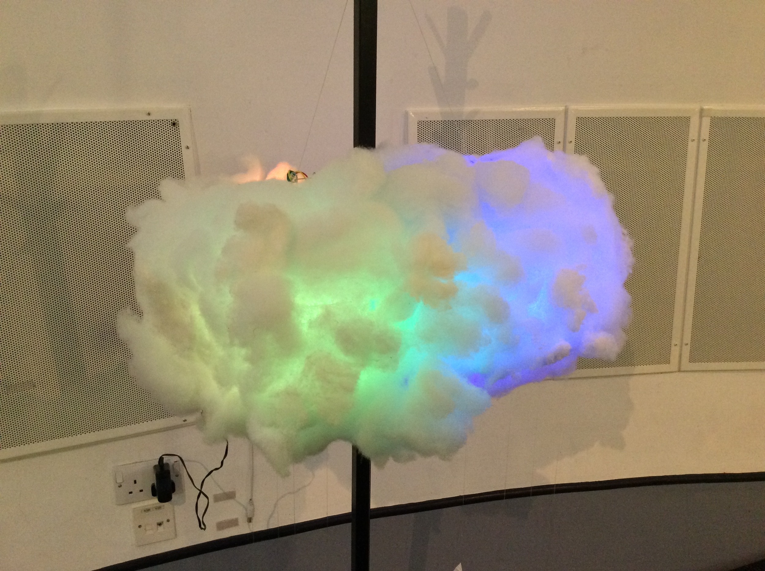
I've been wanting to make a cloud lamp for ages at Three Ways and there are a tonne of tutorials online if you want to follow one of them. I wanted to have a remote control for mine but didn't really want to bother with decoding IR or RF signals whilst trying to do lighting animations. I have used those key fob remote controlled relay modules before, but its massive overkill to control an Arduino pin. I spent a long time looking for a remote module that could control 5V pin logic and sure enough found one that is made by Adafruit, but unfortunately it is on 315MHz which is illegal to use in the UK. Seeing as it is the military channel I didn't want to mess with that really and couldn't find any UK options until I found this amazingly retro thing!
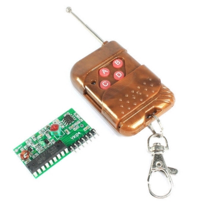
I found it on the 'Flux Workshop' eBay shop for £5.29 which is great for the time and extra hardware it saved me. I have not tested it extensively yet, but it seems to do what I want it to, is on 433MHz which is UK friendly and is the only option besides rolling my own apparently.
Anyway, we now have a way of selecting between 4 presets remotely so I can hang the cloud out of reach, which is good because it would be shredded in seconds!
I'm not sure what I am gong to do about dusting yet...
Paper craft electronics birthday card
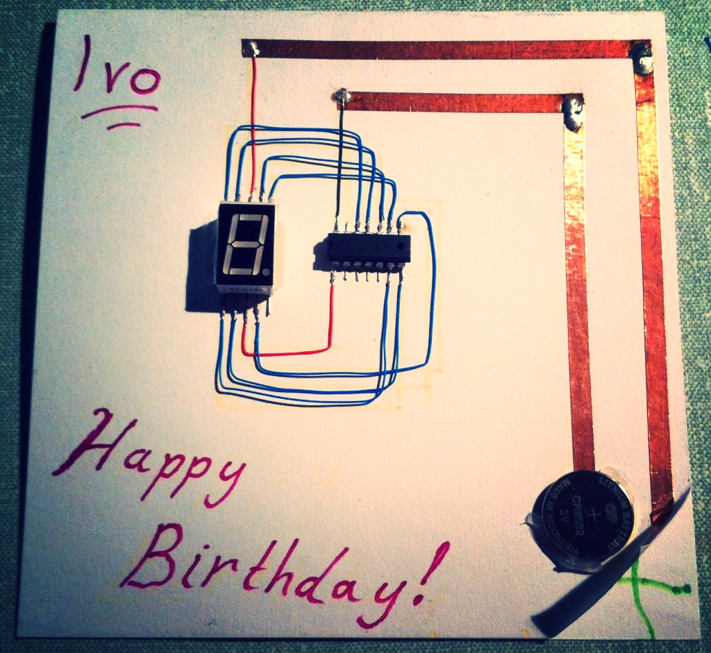
It is my sons 7th birthday today and it has become a tradition to do a paper craft electronics card for him. These have tended to get a bit more complicated every year so there is a warning there to start simple! This one uses an ATtiny 84 chip programmed via an Arduino to run a seven segment display from a 3V button cell. I used very thin kynar wire and copper tape for the connections to make it count up to and flash his age. Definitely one to do before they reach double figures!!
It would be great to print the circuit outline onto the card to scale and do some nice design on the computer, my drawing (and writing!) skills are somewhat lacking!
A first look at the BBC micro:bit
We received some of these cute little ARM based boards aimed at helping teach STEM to Year 7 children. They are really easy to use with a variety of coding environments and are great fun, but can do some pretty serious stuff too. The ring pin outputs are good for croc clips, banana plugs and conductive thread and you can access the other pins with an external edge connector.

It has an accelerometer, a compass and BLE and the coding environment has a great simulator for testing your programmes before you upload.

I will report back when I have done some more playing...
Designing electronic instruments - 6
We have been having a bit of a hiatus from developing hardware for the orchestra project at Threeways School for multiple reasons. On re-engaging with the project we started examining the issues we often have with developing accessible instruments. One of the main things we focussed on was the fact that we always have to create new software when we want to try out some hardware, whether it be an existing device or something bespoke. Wouldn't it be great if we had some kind of modular system that we could plug any bit of hardware into and map its controls to various sound generators/effectors, parameters etc... To some extent with a Max patch to read the incoming control data and a Live template to do something with the data, you can do this. However, if we want to make stuff that can be accessed by anyone, or even stuff that is built in to an embedded system then we may want to avoid using Live and create something that can work as a Max read only patch.
So... with all this in mind we have started developing MAMI, Modular Accessible Musical Instrument. This is kind of a mammoth undertaking in catering for any kind of input, various outputs and making it extremely flexible and routable so we will ultimately focus on our own immediate usage requirements, but with a view to making something that can be built upon long term. At the point of writing I have built a system with which you can dynamically create devices and assign input receivers within those devices, I have focussed on Human Interface (joysticks, keyboards, games controllers etc) devices so far and am moving on to Serial input. I am viewing every controller as having combinations of analogue (sliders, knobs, joysticks, pressure sensors etc) and digital (buttons, keys etc).

Needless to say, it will be a while before a first release !
Designing electronic instruments - 5
Following on from post 1, 2, 3, and 4 on this project.
We met on Monday to take a look at the few modifications to the Filter Box and to see if they improved how the instrument felt and worked in the hand, we also looked at the Pressure Box.
Filter Box
A couple of the things we changed were:
- Moving the force sensitive resistor (FSR) to the left which meant that it sits under the hand better and enables a natural pressure to always be present
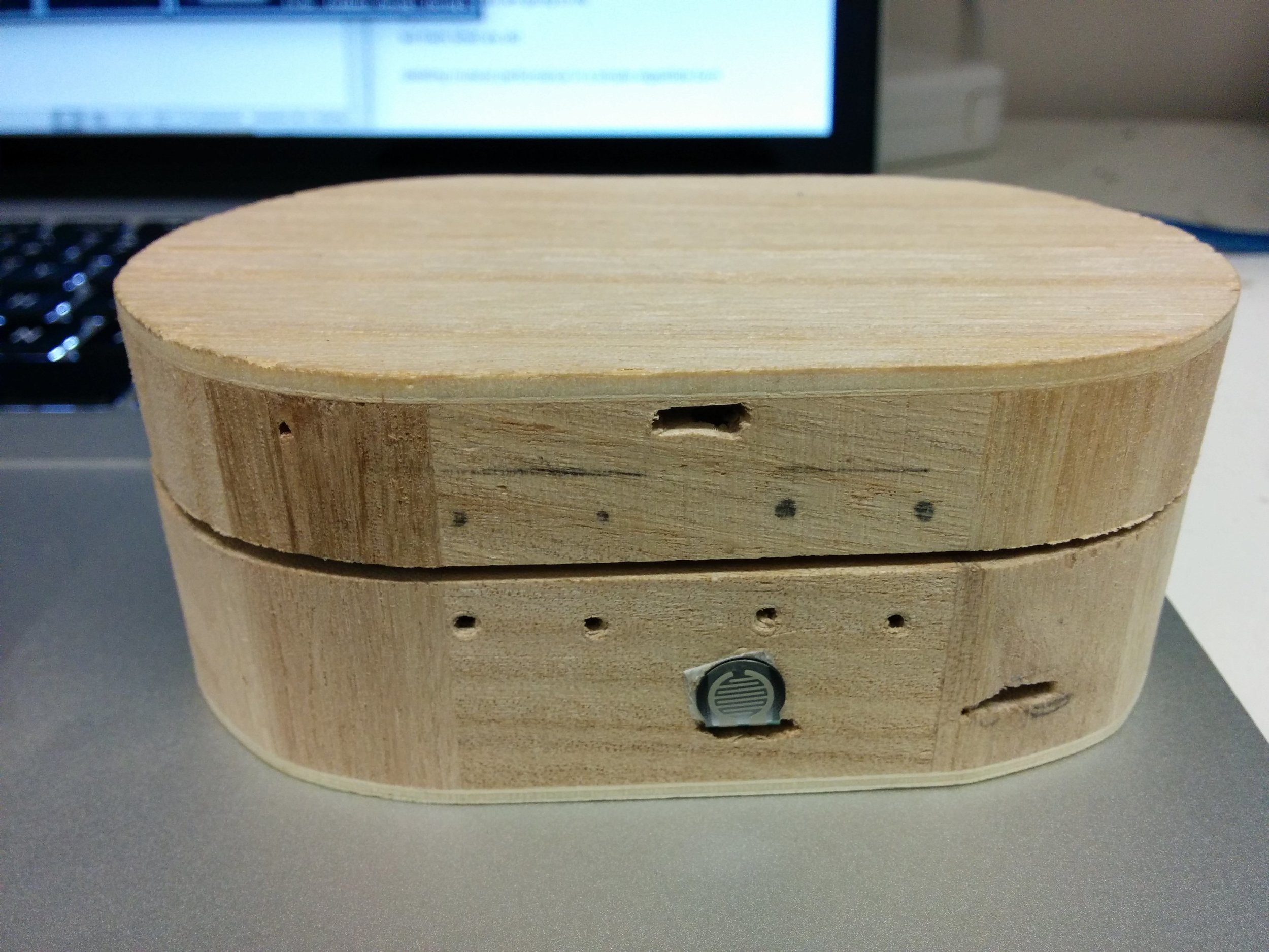
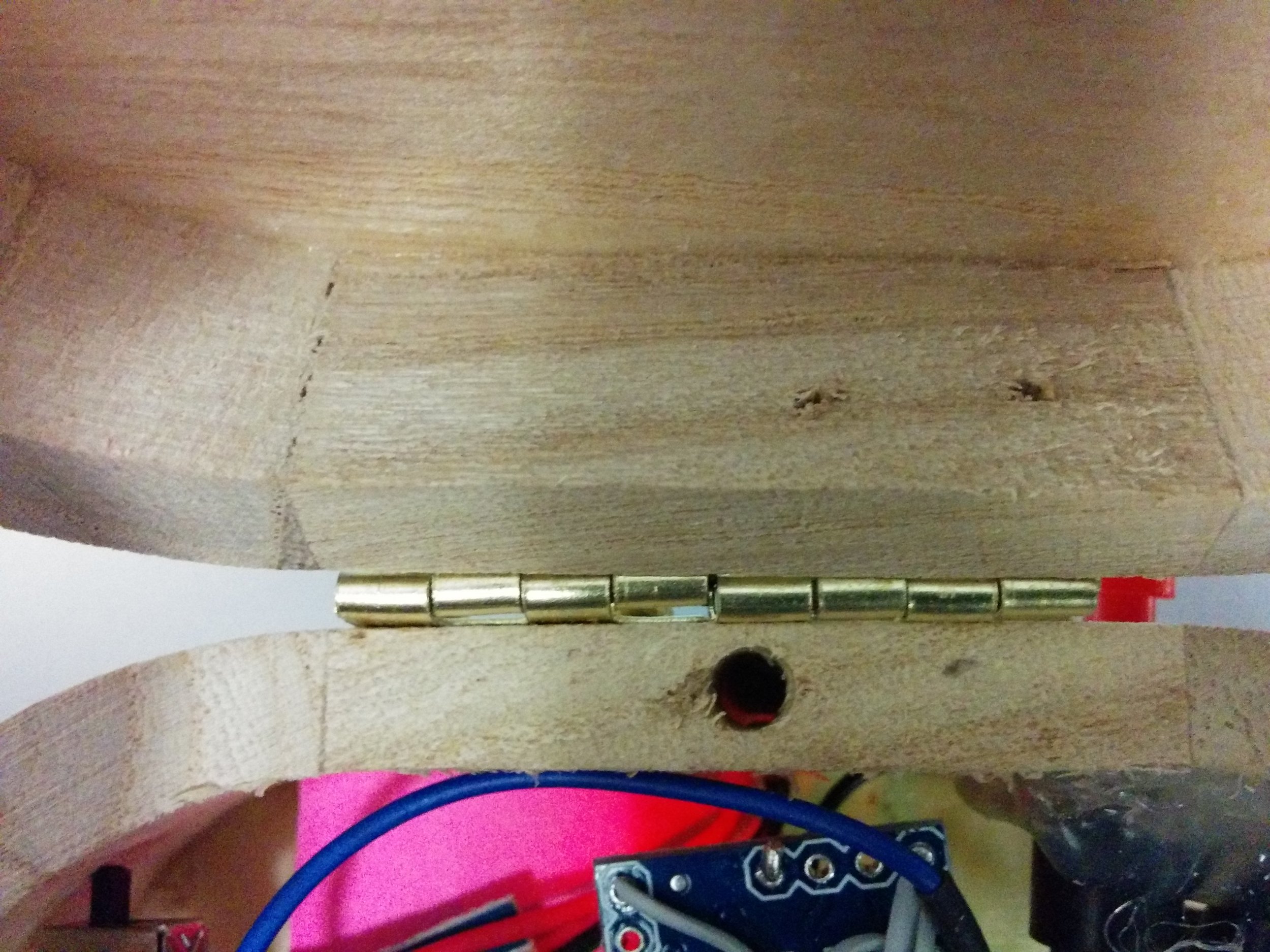
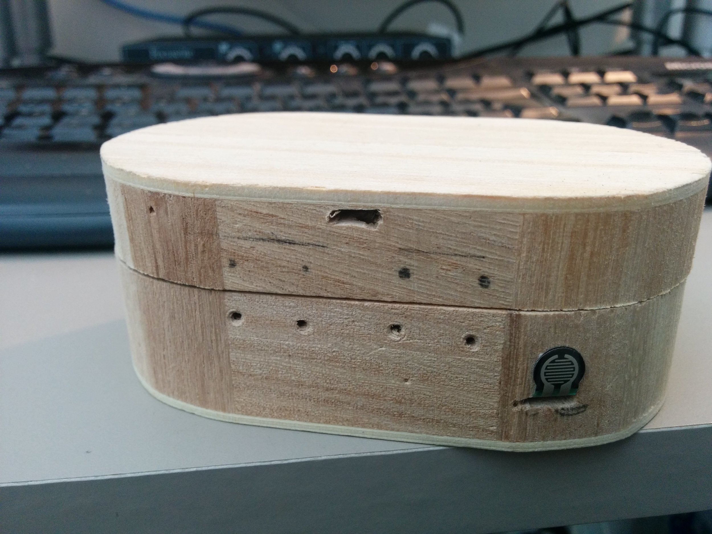
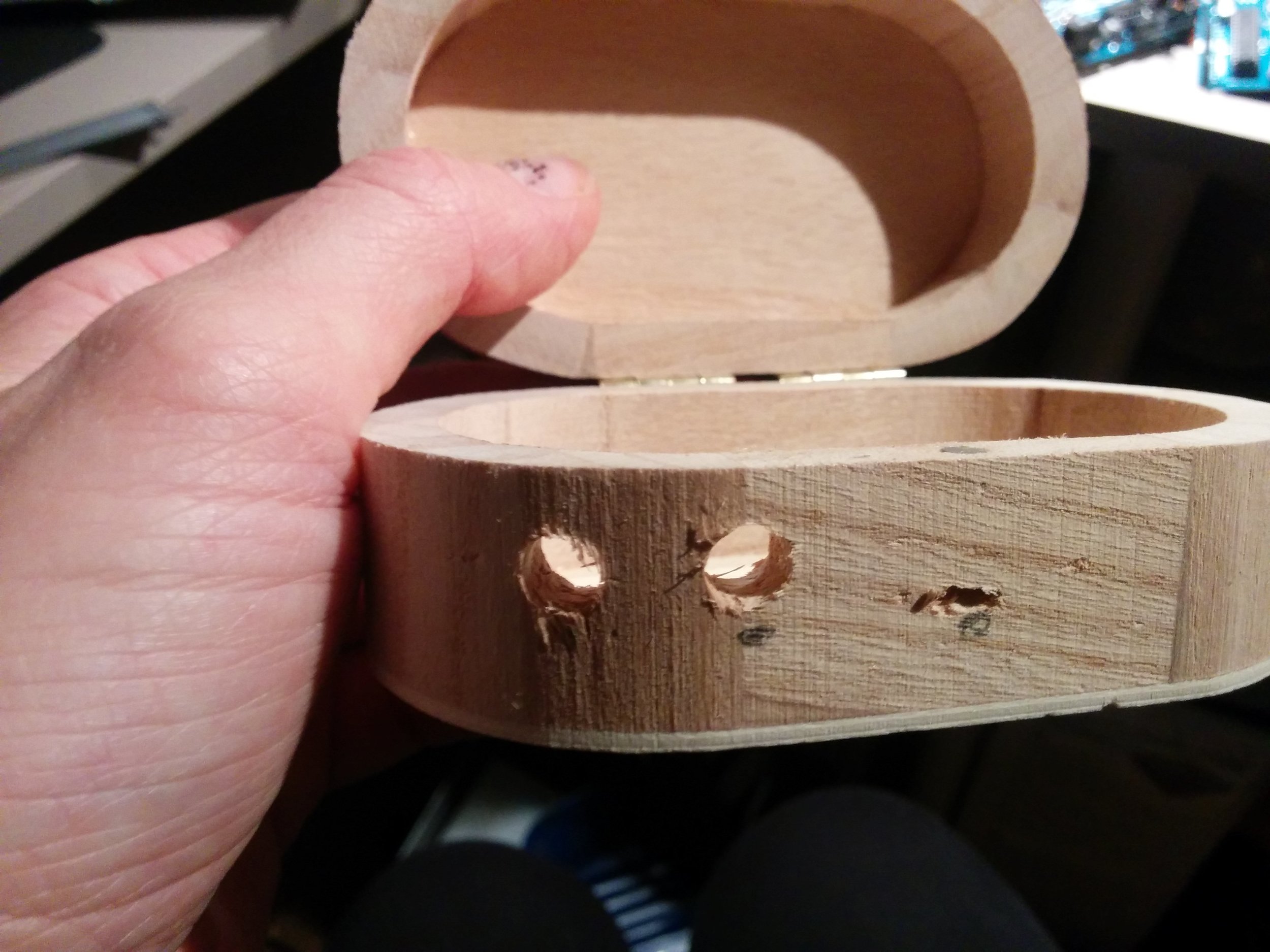
- Moving the light dependent resistor (LDR) to the back middle where the box hinges, at the bottom of a drilled out hole, so that the box has to be opened fully to trigger the sensor and it is not as sensitive to ambient light changes
We had a play about and made the following points:
- FSR for now in much better position as is accessed automatically by hand when squeezing and can be used by finger too.
- LDR in better position drilled down the back to give more uniform reading in changeable light scenarios- might also work to use a led strip so the whole thing is self contained- a nice feature is that moving towards the light can be used as a tool to give expression
- might be nice to extent the functionality with an accelerometer so that physically shaking the box could be connected to audio parameters, there would be a lot of data to play with!
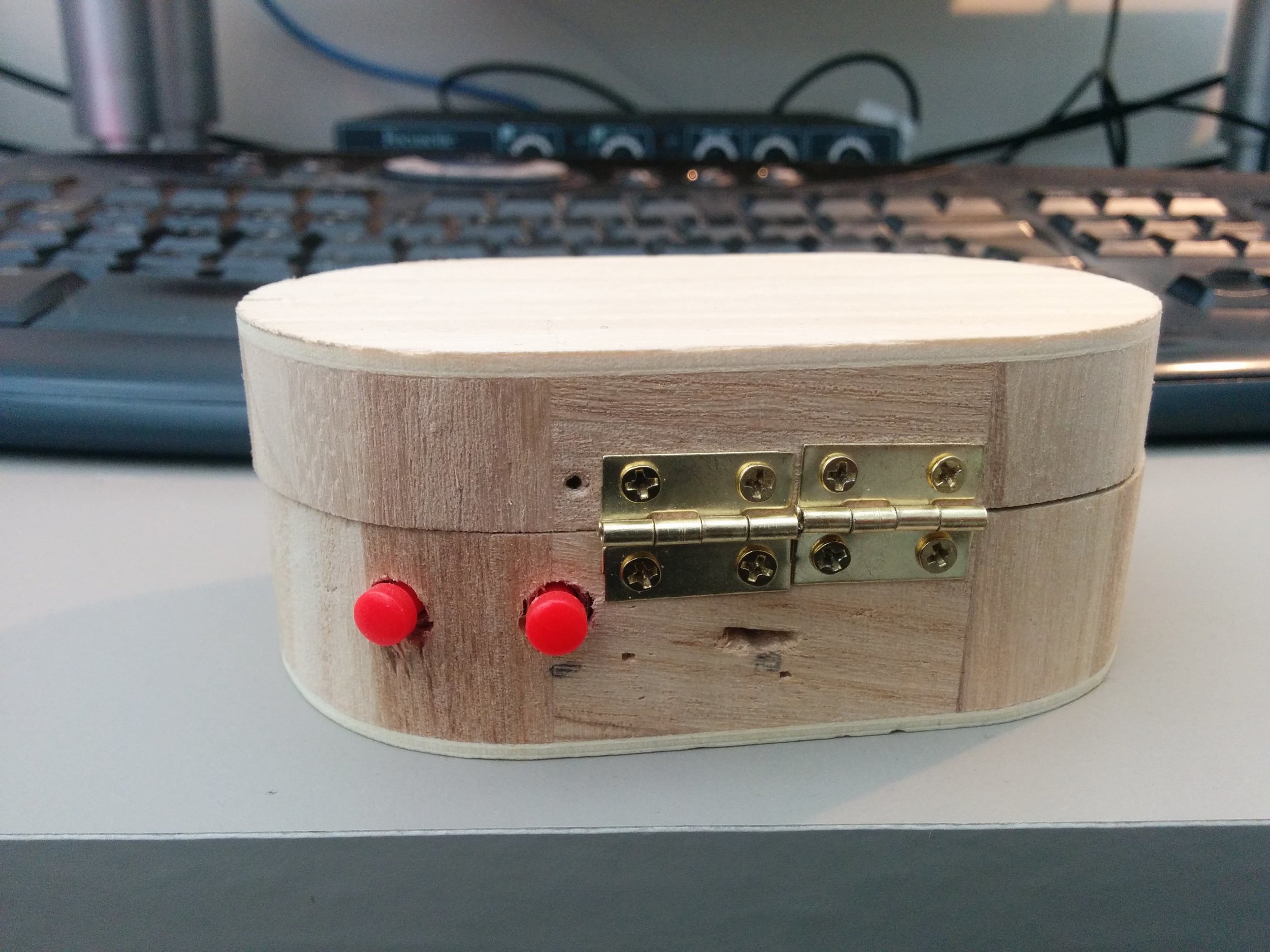
- buttons still a bit dodgy- one is more flush to the box than the other so the desire is to overcompensate and push in the other one really hard. Will try the new bigger arcade style buttons, they are more rigid but have an easier action and less resistance when the spring is removed
Pressure Box
We also took a look at the Pressure Box and ran it into Max to take a look at its responses:
- Needed more foam and perhaps a layer of more solid foam
- The piezos are fine with short sharp hits but do not respond to long pressure pushes which is not ideal. They do give a response from pressure after idling at 0 for a short time, but not until releasing them. Kind of the opposite to what we wanted to happen. This might mean that the piezo is not quite right depending on the type of instrument we want to design sonically for. A more percussive application could work well as the response to this action seems to fit with the action itself, however if we want to be able to press down slowly over time then another solution must be found!
We shall keep exploring and testing!
Designing electronic instruments - 4
Following on from post 1, post 2, and post 3 on this project.
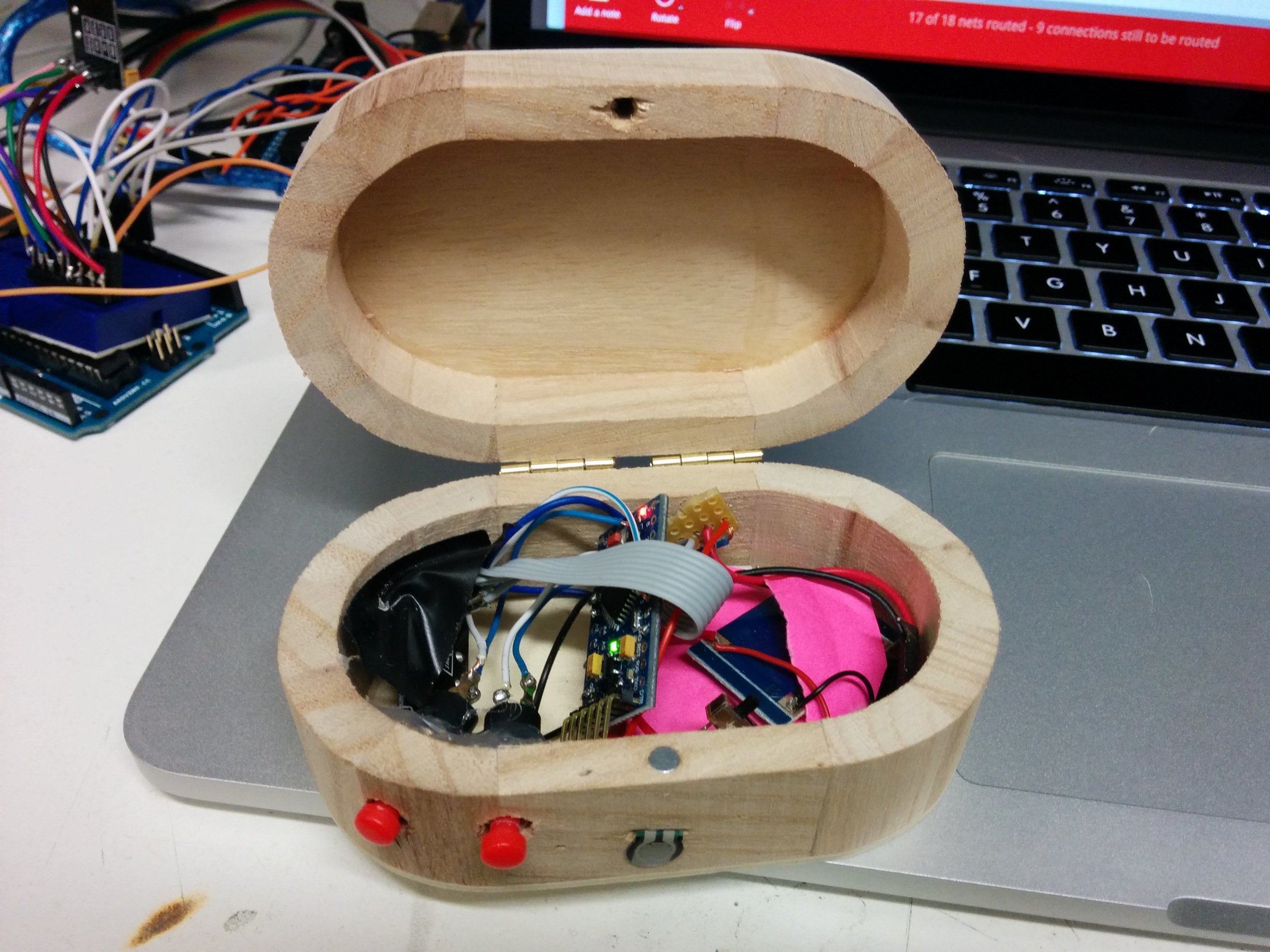
We met on Monday to take a look at the modifications to the Filter Box and give them a little test with the Max patch that Luke has been developing, and then I went away to make the modifications.
Filter box testing:
A couple of modification were discussed to make the box more ergonomic and natural to use and hold and that will allow for easier interaction with the inputs the box offers.
These were:
- Move the hinge to the other side of the box to enable holding and opening like a book
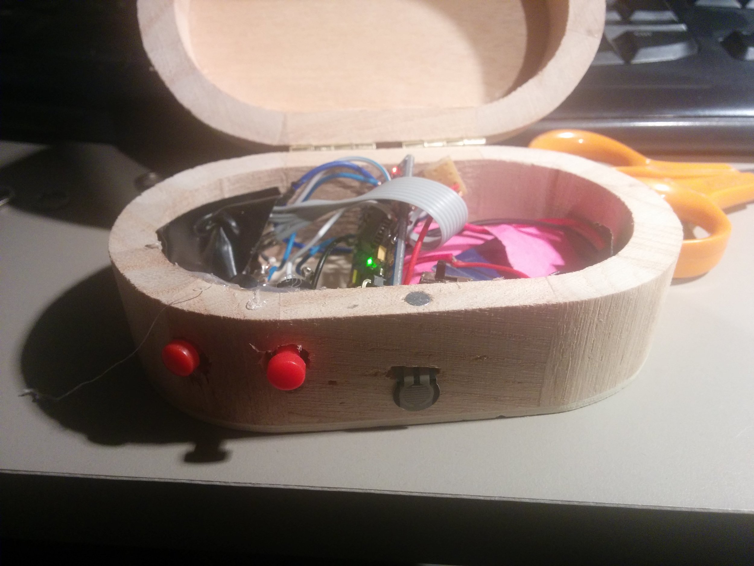
- Change the button style as they are not working quite right in fitting nicely to the finger or giving adequate feedback, maybe to tiny arcade style buttons that accommodate fingers with a dip, or custom made buttons attached to a micro switch
- The pressure sensor is in an awkward position on the front making it difficult to use it with the buttons so move to back where the thumb pad of the hand naturally presses against it

We met again the following Monday to discuss the above modifications.
We found it was still difficult to access the force sensor and the buttons at the same time. Also to trigger the sound the button and force sensor have to be used at the same time so what might be better is to leave the sound level high until you press the force sensor which will then lower the volume, this would mean there would be less chance of a player pressing the buttons and thinking they were not playing it correctly or it was not working.
There is also an element here that could play into having to control and mould a sound with the instruments, Luke has mentioned in the past creating an instrument that you would have to fight against in order to play. This could be a good opportunity to explore a concept like that, to have the instrument playing and you use the inputs to bring the sound in order.
We also discussed the possibility of the light dependent resistor being a little bit volatile in performance situations as there are potentially flashing lights or light changes that could trigger the instrument and disrupt the players sense of cause and effect. Also any photographs taken with flash could trigger the sensor. This will require testing to see how much of an issue this would be. One suggestion is to move the sensor down a well next to the back hinge of the box so the box will be less responsive until it is more fully open......a little more fiddling required :)
Designing electronic instruments - 3
Following on from post 1 and post 2 on this project.
On Monday we met to discuss the latest prototypes of the Filter Box and the Pressure Box.
Filter box:
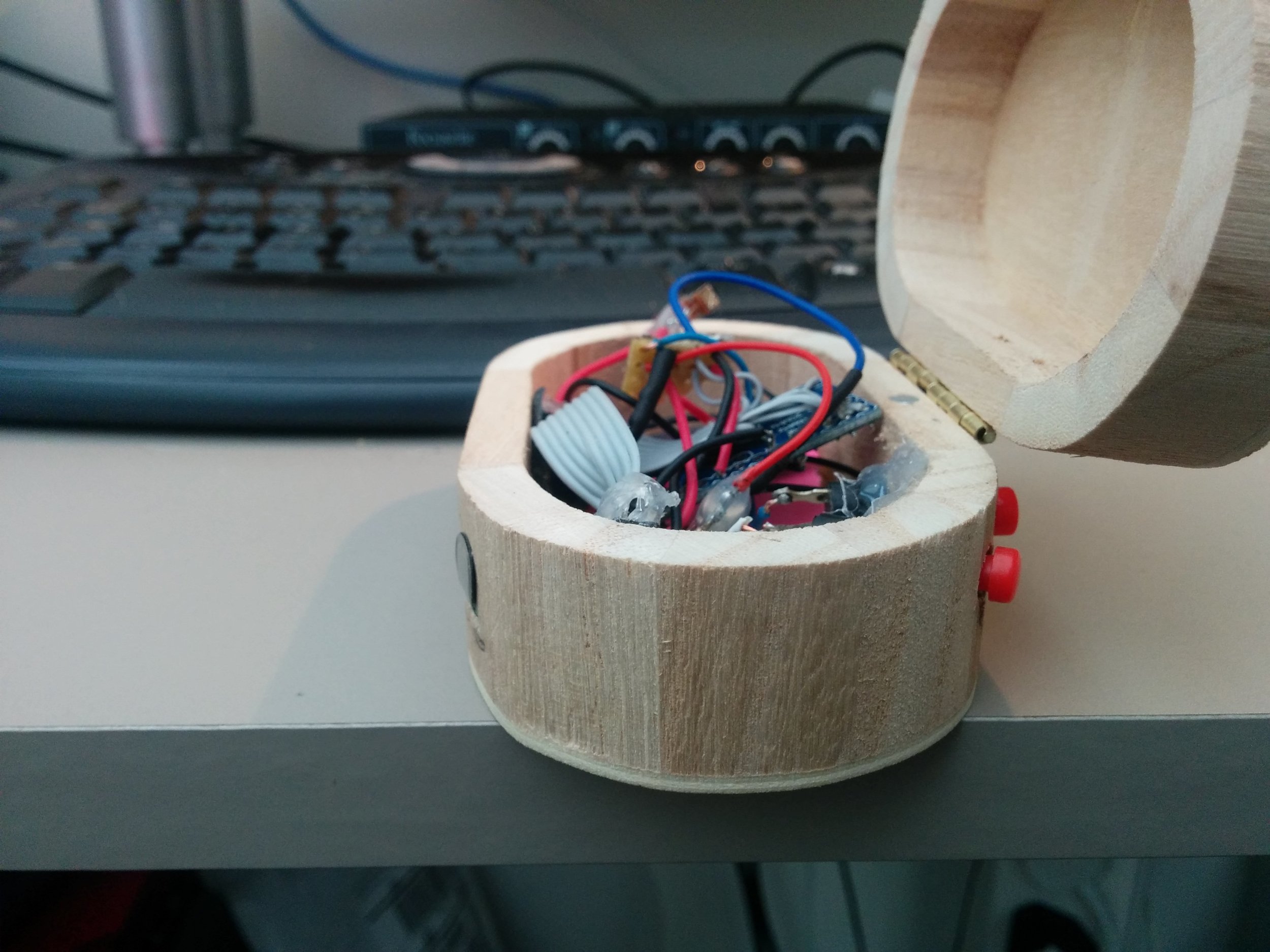
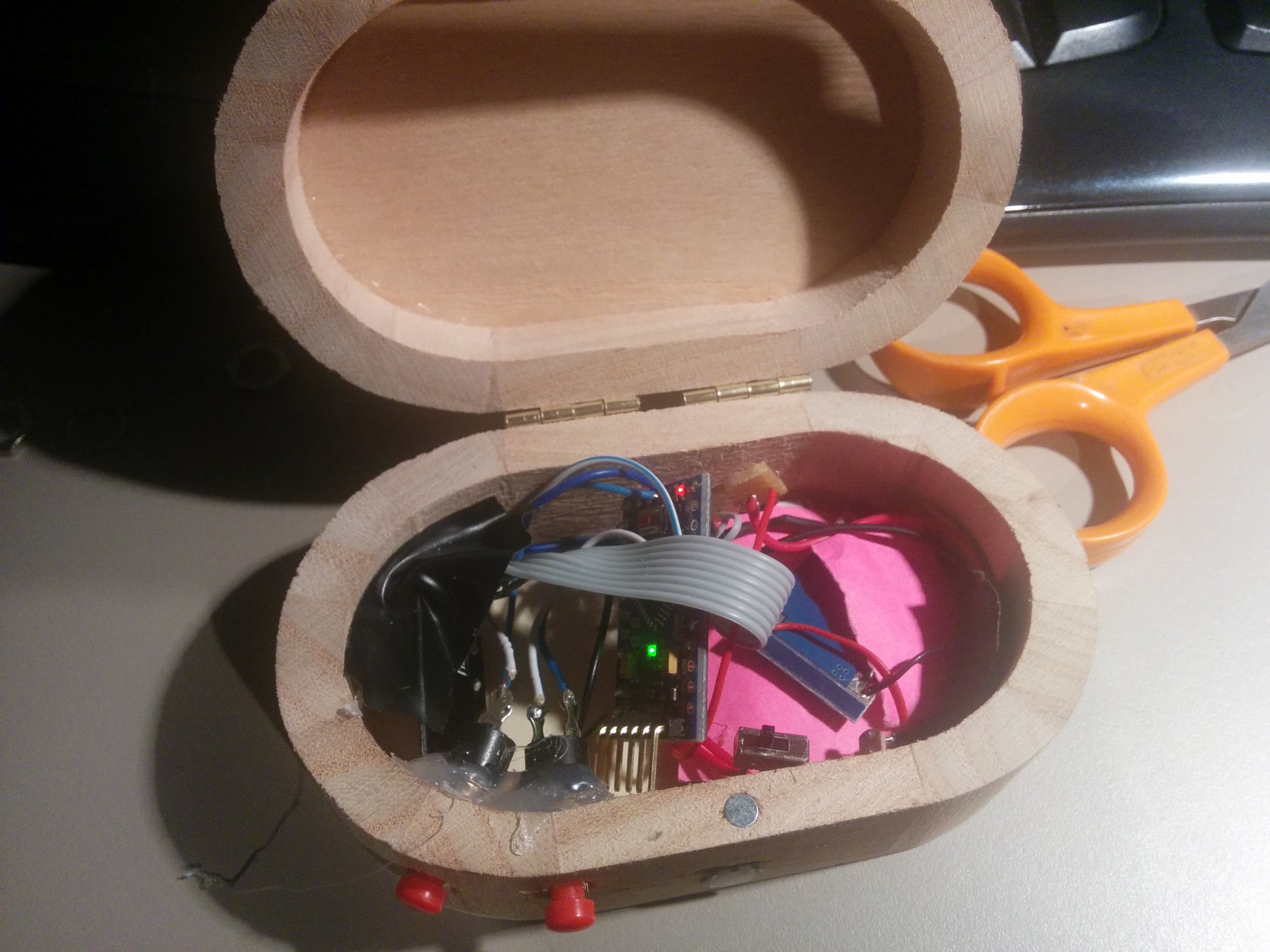
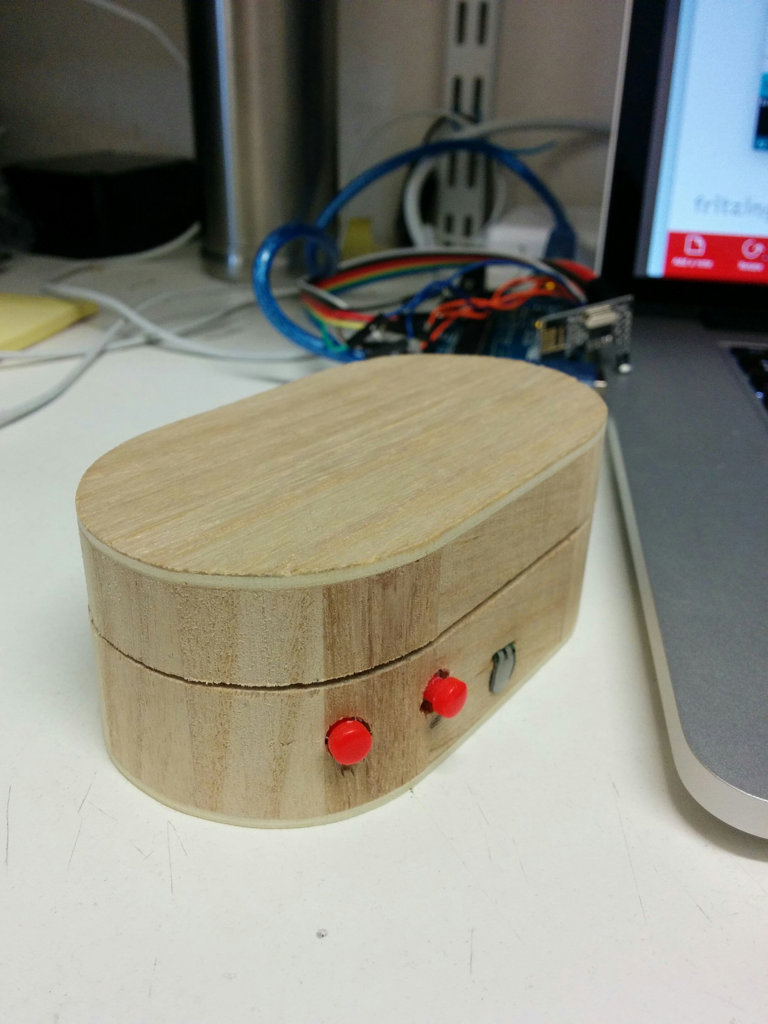
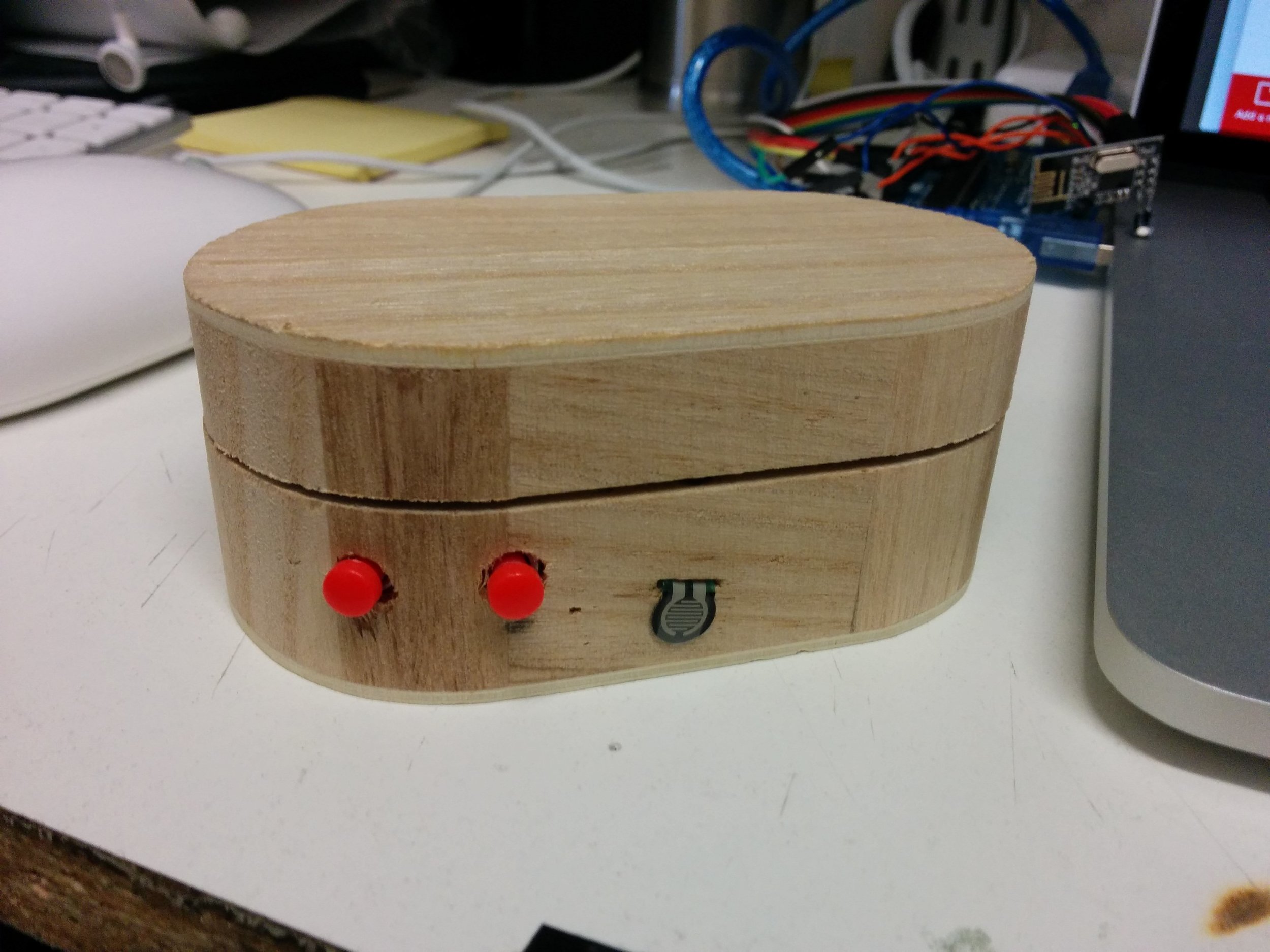
We had selected the small oval box as the one most suitable for the Filter Box and I set to work adding 2 valve style buttons and 1 force sensitive resistor to go alongside the light dependent resistor already installed in the prototype.
Parts added to existing prototype:
1 x Force sensitive resistor (FSR)
Circuit:

A note on the resistors for the buttons; no resistors are needed on the buttons if you enable the inbuilt resistors in the Arduino, you can do this in the code uploaded to the board. We did not use resistors on the buttons and so the code below will mean that the buttons are considered to be high or on until pressed which will then turn the input to low or off. So these buttons send a 1 when not being pressed and a 0 when pressed.
The Code:
https://github.com/lwoodbury/AMI
Creating the Filter Box
The box required 2 more holes drilling to match the size of the valve fitting, these then had to be glued into place to secure. A small slit had to be drilled and filed to allow for the FSR to pass through.
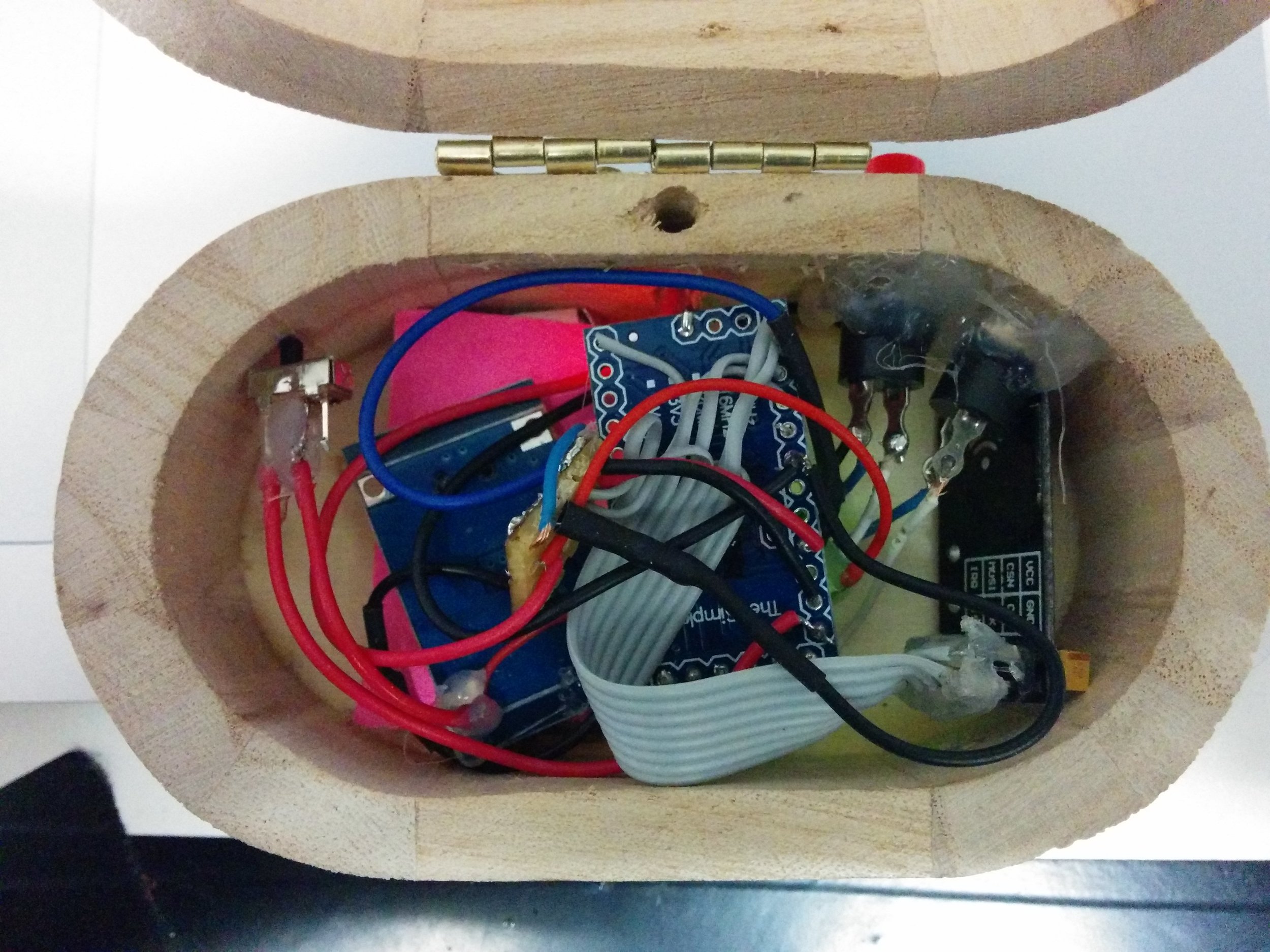
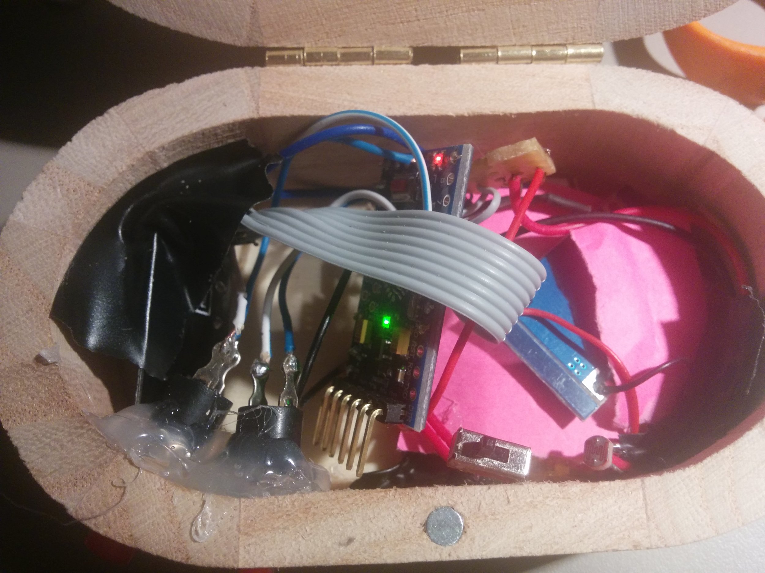
Electrical tape and paper was used to ensure that none of the vital circuitry was touching each other as the box is quite a small space for all the components needed. The Filter Box was then ready for some testing!
The Pressure Box
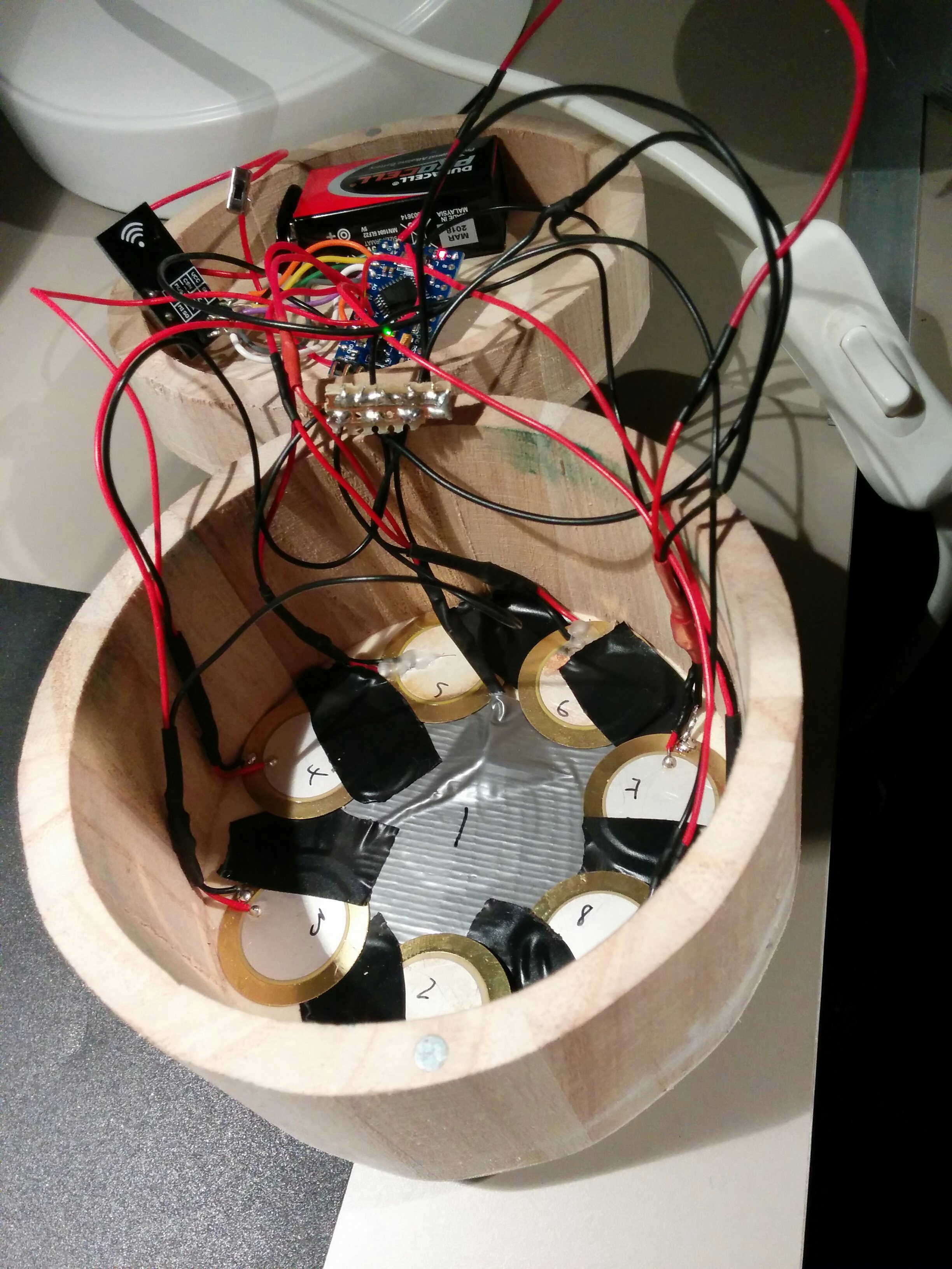
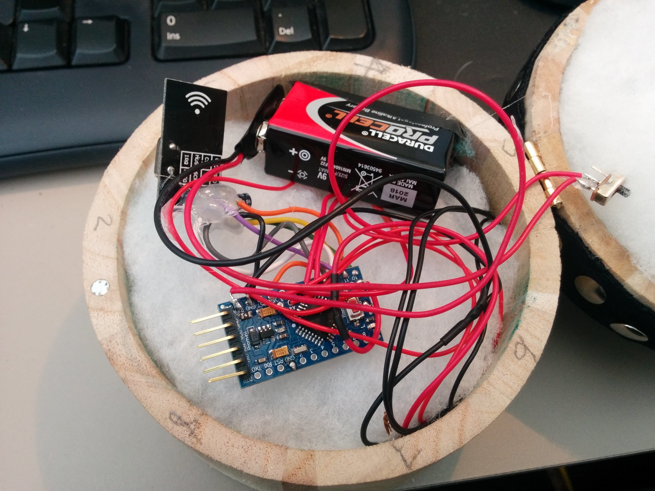
We decided that the bigger rounder box would suit the Pressure Box and so we went about designing the gubbins that would make it work. At the moment whilst awaiting deliveries for lithium rechargeable batteries we have stuck with the good old 9v square battery which differs from what is seen in the circuit diagram. The Pressure box uses the same Arduino and radio combo as the Filter Box but we are will be using 8 piezos as analogue inputs instead, 1 large for the centre and 7 smaller for the outer ring. Piezos are very cheap and very sensitive so should give us good feedback as to where on the top of the box is being pressed.
The Circuit:

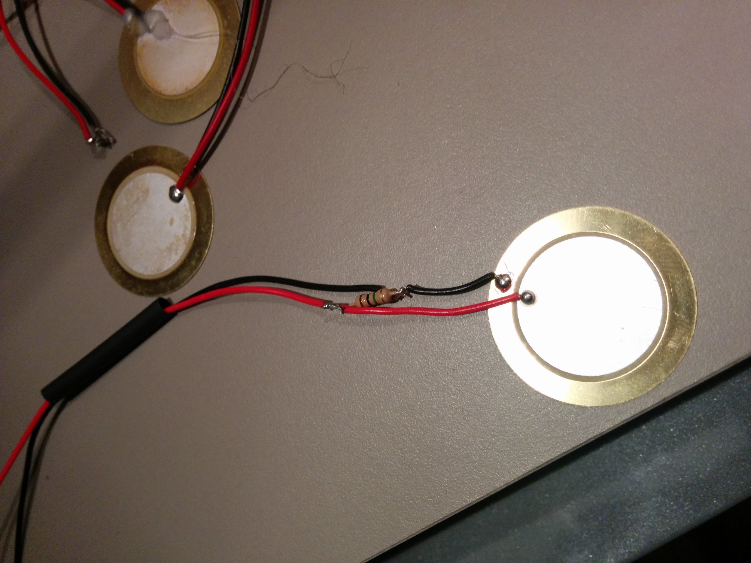
Here is a more simplified view of how each piezo is wired in:

A note about the circuit: The software used to draw up the circuit didn't have the exact same Arduino board as we are using so the green section to the left of the Arduino board is simulating the analogue inputs that are in different positions on the Arduino. The picture below shows more clearly the holes for the analogue inputs (A0-A7) A4 and A5 are the holes above A2 and A3.
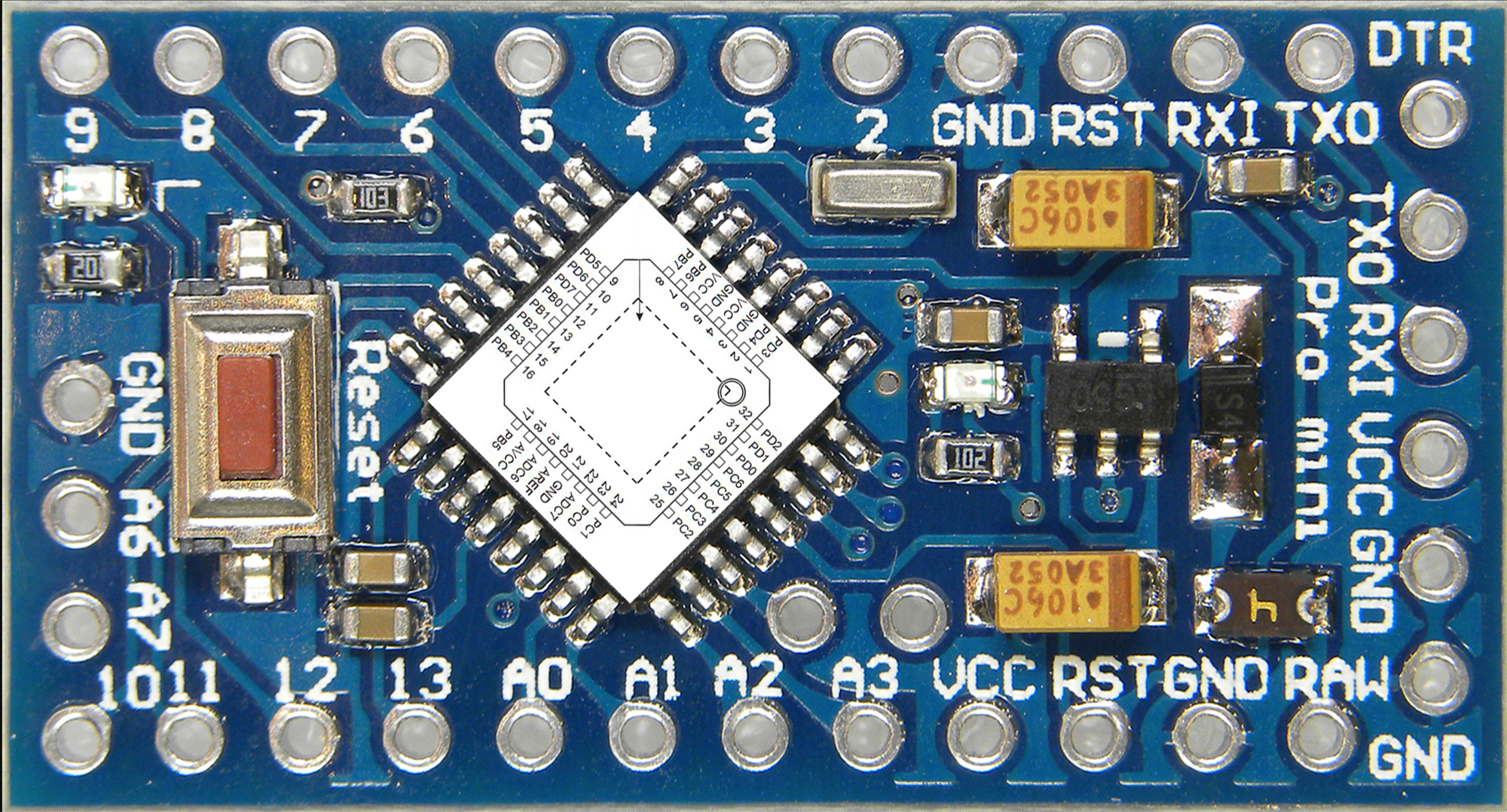
Image from http://www.dominicdube.com/wp-content/uploads/ArduinoProMini000b.jpg
Each of the piezos had to be prepped as they require a 1 MOhm resistor running between their 2 wires as seen in the circuit diagram. The resistor was installed at near the disc of the piezo and some heat shrink was used to seal everything in.
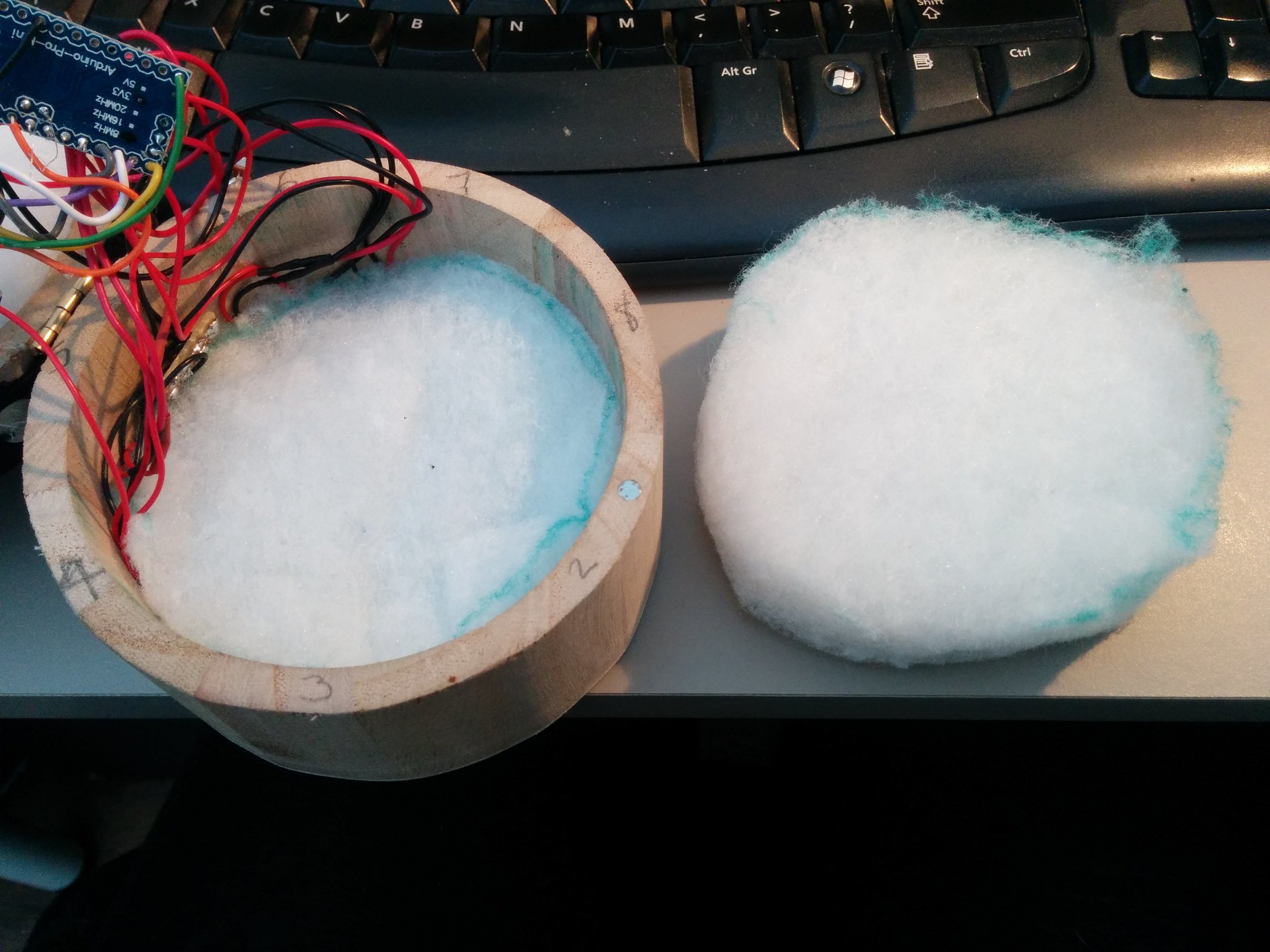
The piezos were then arranged around the bottom of the box with electrical tape to stop them touching. Two layers of thick but airy foam wadding were used to provide the bouncy resistance needed. The components were stashed between the two layers. Once the correct battery has arrived these components should sit nicely over the middle piezo.
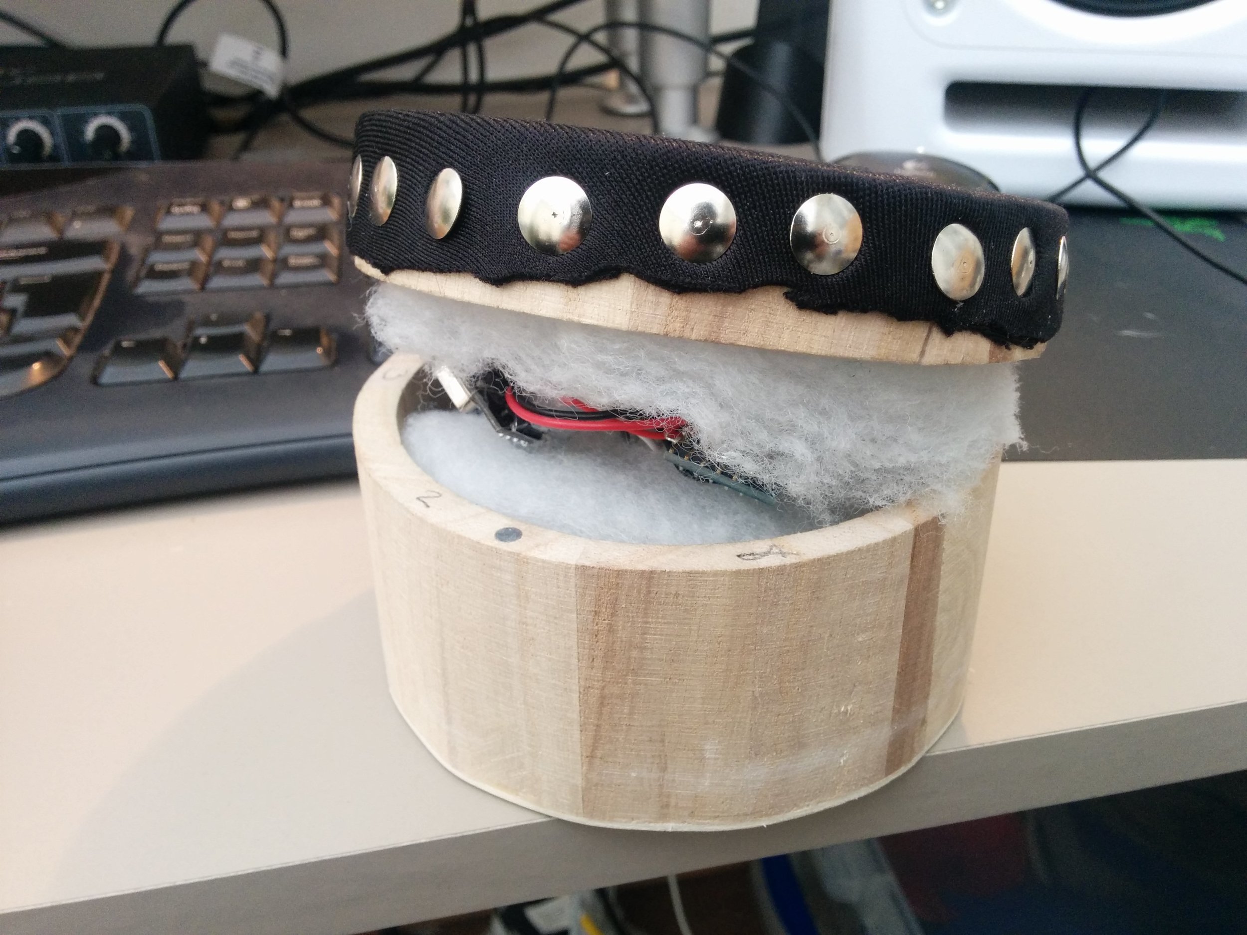
Attention then turned to the lid. We decided it would be best to cut out a hole in the lid thus having a ring of wood on which to attach the skin (tambourine style) and then pin it on the edges with thumb tacks. This would also allow us to put clasps on the side of the lid to attach to the box so as to provide access to the components if needed without removing the skin.
We took to the CNC router to nicely remove the inner lid before adding the skin made from a thick piece of lycra like material folded double.
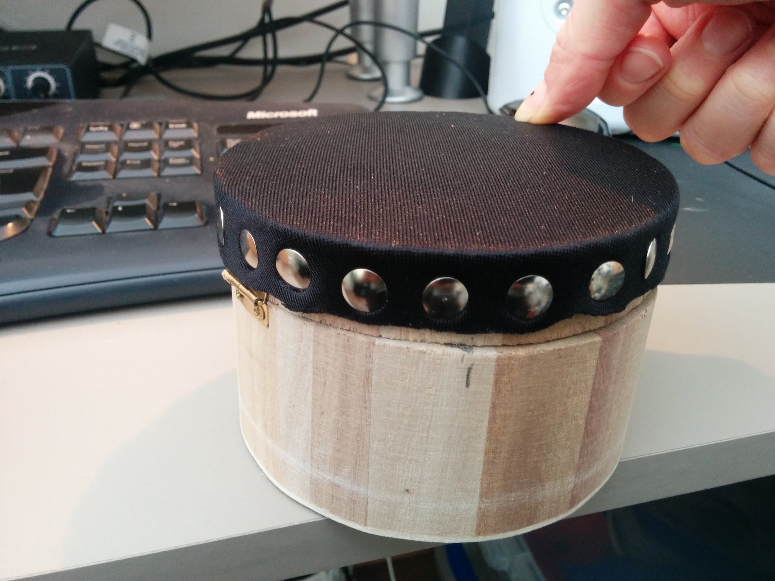
Testing will be done with these prototypes to see what the next steps are........