Workshop 2 resources
We have looked at the digital (on or off) so lets have a look at the analog side of things now. Make the following circuit, paying attention to the fact that we have moved our LED to pin 9 as it has some extra functionality that we want to use (check out the wiggly line next to it!):
The knob is actually a variable resistor, i.e. a resistor that changes its resistance based on where you turn it (called a potentiometer or a 'pot'). You put the 5V in one side, the ground in the other and the middle pin outputs the changing voltage as we move the knob. We can read the varying voltage with an analog pin on the Arduino and use it to control an LED.
Upload the following code, turn the knob and be amazed as the LED fades from off to full brightness.
/*
PotLED - Control LED fading with potentiometer

 The circuit:
 * Potentiometer attached to analog input 0:
 *  - center pin of the potentiometer to the analog pin
 *  - one side pin (either one) to ground
 *  - the other side pin to +5V
 * LED anode (long leg) attached to digital output 9
 * LED cathode (short leg) attached to ground (via a resistor!)
 *
 * Created by Luke Woodbury
 * 6 Jan 2016
 * This code is in the public domain
 */

// Define the pins globally
int sensorPin = A0;    // select the input pin for the potentiometer
int ledPin = 9;      // select the pin for the LED

void setup() {
  // initialize serial so we can print to the monitor
  Serial.begin(9600);
  // declare the ledPin as an OUTPUT so it is given more power
  pinMode(ledPin, OUTPUT);
}

void loop() {
  // define a local variable and read the value from the sensor
  int sensorValue = analogRead(sensorPin);
  //remap the sensor value from 0-1023 to 0-255 for LED PWM fading
  sensorValue = map(sensorValue, 0, 1023, 0, 255);
  //print sensorVal to serial monitor
  Serial.println(sensorValue);
  //write value to LED pin as PWM
  analogWrite(ledPin, sensorValue);

}
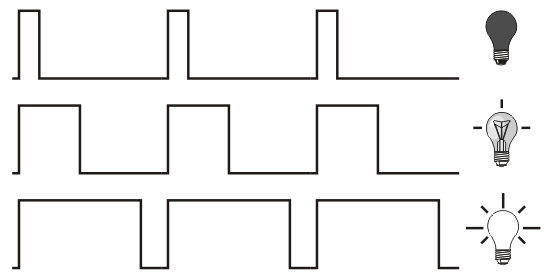
We are essentially tricking the human visual system here. We mentioned earlier that the LED is a digital component, either on or off, so we can't fade it right? What we do instead is turn it on and off really fast, the more it is on, the brighter it looks, the more it is off the dimmer it looks. We are essentially sending it this sort of voltage output, where the high line is 5V and the low line is 0V:
This kind of output is called PWM (Pulse Width Modulation) and as well as fading LEDs with it, we can use it as data to control things like servo motors (more on that in the next workshop). The PWM pins are the ones with wiggly lines, tildas, next to them and we can output it with the 'analogWrite' function as you see in the code. We output PWM in this case as a number between 0 - 255, but the analogue in value (the reading from the knob) is between 0 - 1024 so you can see some remapping going on in the code too. If you click the little magnifying glass in the top right corner of your Arduino window you will see the printing of these numbers defined by the 'Serial.print' function in the code.
Have a look through the notes in the code and see if you can follow what is going on.
Lets have a look at using PWM with servo motors...
Workshop 1- Hello World!
Simple use of a button (a digital input) to turn an LED on
Workshop 2 - Analog inputs/outputs
Reading a fader/knob/sensor (analog input) to fade an LED
Workshop 3 - PWM and servo motors
Control a servo motor using Pulse Width Modulation
Workshop 4 - Fritzing!
Having a look at circuit design using Fritzing
Workshop 5 - Soldering
Some tips on soldering
Workshop 6 - Serial Communication
Exploring how to communicate with the computer via serial
Workshop 7 - Controlling Max MSP
A look at Max MSP and how we can speak to it from Arduino
Workshop 8 - Making a video system
A look at some of the built in video modules of Max and using Arduino to control them
Workshop 9 - Max to Arduino
Going the other way and using a Max user interface to control Arduino hardware


