At Three Ways School we recently purchased an Optoma ML750ST projector for dedicated floor projection. This is an awesome little projector, it is tiny, has a short throw lens and an LED light source. I'm using it with an overhead IR camera to do some interactive floor projection which I programmed in Max MSP. Check the video:
Designing electronic instruments - 2
Following on from this post.
On Monday we met to discuss the first prototypes of the two instruments we wanted to explore as detailed in the previous post.
The Filter Box
We took a look at the first Filter Box prototype as seen in the pictures below which was set-up in a temporary box for testing of the sensors. I bought several small wooden boxes to try for size, shape, and general ergonomic-ness when holding, and to enable discussions as to what might be good features and functionality to have in the box.
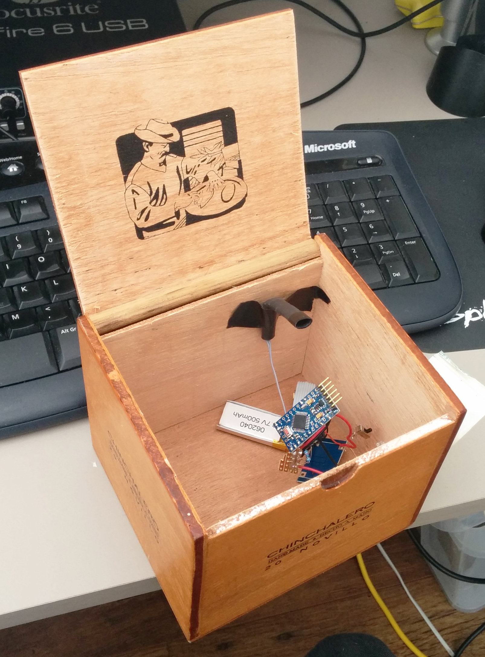
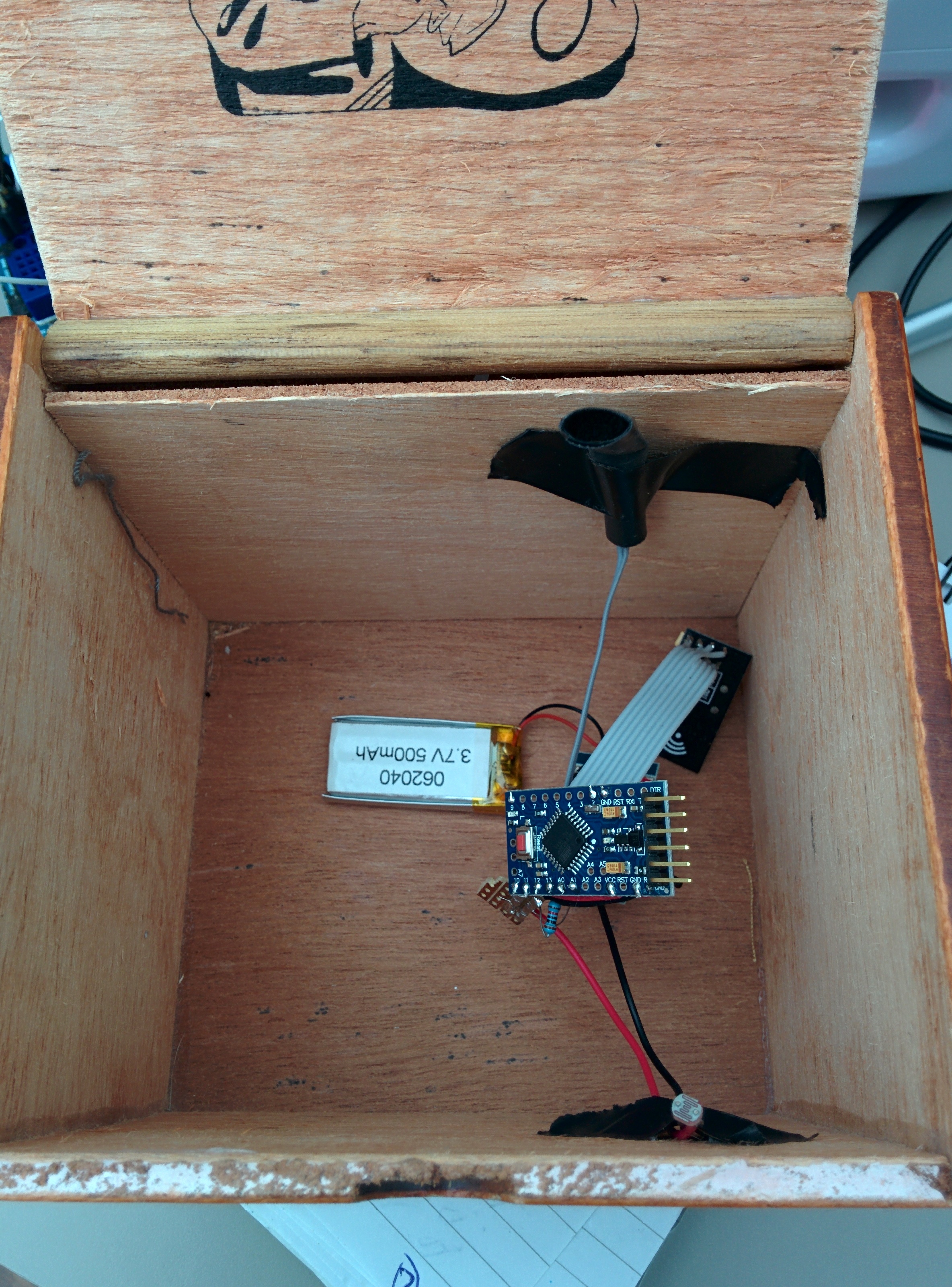
Our idea was to create a wireless filter box. I wanted to use some of the nrf240l1 radio modules I have acquired as they provide a very cheap mechanism for wireless communication, and there are lots resources available to make them work with Arduino. A detailed tutorial on using Arduino + Nrf24l01 running into Max/MSP software can be found on my website here.
Discussing the box!
We discussed:
The wooden boxes I had purchased and selected a small oval shaped one as the best shape and size to fit in the hand.
Buttons- having some (x2) to enable more functionality- options included click buttons that would provide tactile feedback when depressed or valve style that would more naturally mimic an interaction with an instrument such as a trumpet, like a valve, these would give feedback not as obviously as a click but more suited the instrument paradigm.
Adding a force sensitive resistor (FSR) that could then be pressed harder or softer to achieve some of the effects you would with other instruments such as when fretting a guitar, and allow expression through fingertip movement and pressure of the hand on the box. The mapping of the FSR could then be naturally connected to something like the amplitude of the sound so when pressed harder the sound would be louder, again going with what a player might naturally expect from an interaction of that style.
Light dependent resistor (LDR) this worked well as a mechanism to control some sort of filter, or for example the mute of a trumpet, the cutoff frequency of the sound or the volume. This is taking the movement of the opening and connecting it to any kind of parameter that might need fine movement and can be used to get effects like vibrato and tremolo. A parallel can also be drawn between something like scratching (dj style) by opening and closing the lid, and when connected to a filter controlling some element of feedback, using noise as the sound generator. We had a little play with using the light dependent resistor to control the cutoff frequency on a filter over sounds and using the motion to trigger MIDI notes but felt that the latter did not really play into the strengths of the opening and closing of the box as much as the controlling of an effect.
The aim with the filter box was to create something that when held in a natural position would allow access to the 2 buttons and the FSR as well as facilitating the opening and closing of the lid so that the elements could be used in conjunction with each other and separately in an ergonomic way.
The Pressure Box
We discussed the pressure box and using an array of piezos arranged around the bottom of the circular wooden box to create 8 potential pressure points. The Arduino pro mini we are using in the instruments allows for 8 analogue inputs so would suit this set-up. The box can then be filled with foam and topped with a soft tactile yet spongy material such as neoprene, or potentially some sort of skin stretched over the top in the style of a tambourine and secured down with pins. Being that the piezos are very sensitive to vibration there may be some cross talk between the 8 units but this could provide useful for expression. The sensitivity of the piezos allows for tapping the box to trigger or modulate the sound also.
Future boxes
The hexagonal box though not used yet could potentially feature a new mode of interaction for each of its faces to allow a player to choose their preferred interaction mode and mechanism, this may be one for future exploration.
Next Steps
I will now review what we have discussed and implement them into some more prototypes!
Working with eTextiles
eTextile quick demo from Luke Woodbury on Vimeo.
Today at Threeways School we met with some Bath Spa University art students to discuss a project that looks to explore eTextiles. We will be working towards an installation that will be explored by the children and young people at Threeways in the Sensory Studio in March. I wanted to rig up a demo that made use of conductive thread and a micro controller designed for wearable projects so I ordered an Adafruit Gemma (essentially a wearable Arduino) and some sewable Neopixels and went on the fantastic Adafruit website to look at the wearable projects for inspiration.
I found this tutorial for a pixie dust bag which would require minimal sewing and would be easy to put together for a demo. I only had 4 flora LED pixels, but I figured this would be fine. I also didn't want to use a capacitive sensor, but instead wanted users to have to squeeze the bag to change colour. The bag can be held in the hand and it is good dextrous exercise for some of our students to squeeze objects like this so was a nice example. I could have used a force sensor, or made one from velostat, but I opted for using a piezo as it is cheap and ready to use. One of the Arduino examples in the 'Sensors' section is for a knock sensor using a piezo, this would be the basis of my input and I simply needed to swap out the capacitive sensor input and put this in. As the example code says, the circuit is simple too:
* + connection of the piezo attached to analog in 0
* - connection of the piezo attached to ground
* 1-megohm resistor attached from analog in 0 to ground
Parts:
Adafruit Gemma - £7.26
Flora RGB Neopixels - £7.19
Conductive Thread - £3.88 (you can use wires instead to be honest and it would be easier and cheaper if like me you prefer soldering to sewing! As long as you use flexible wire and avoid brittle single core stuff it should last for a while, though may end up snapping eventually.)
Small Piezo - £1.36
A small Lithium Ion Battery - £7.22 (you will need a special LiPo charger too, beware that chargers are often aimed at either above or below 500mAh batteries, though may be adaptable. Check your battery and match it to something suitable.)
1 megaohm resistor
Some cushion foam and a cotton drawstring bag
Total cost is around £20
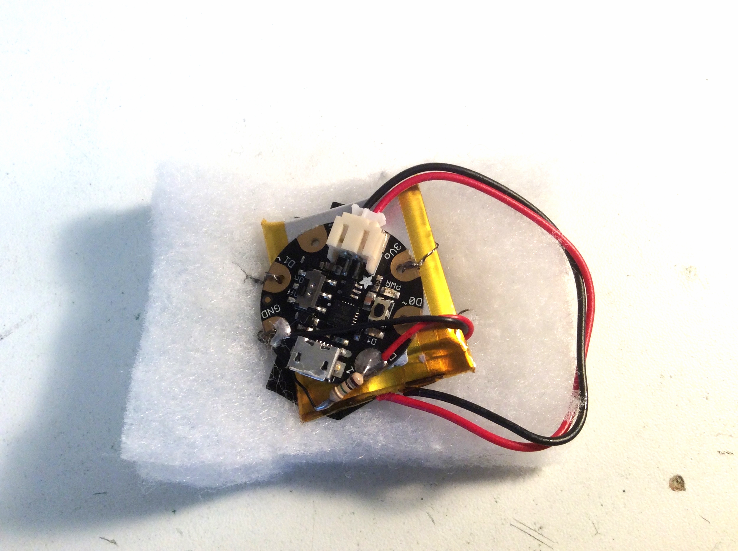
Circuit:
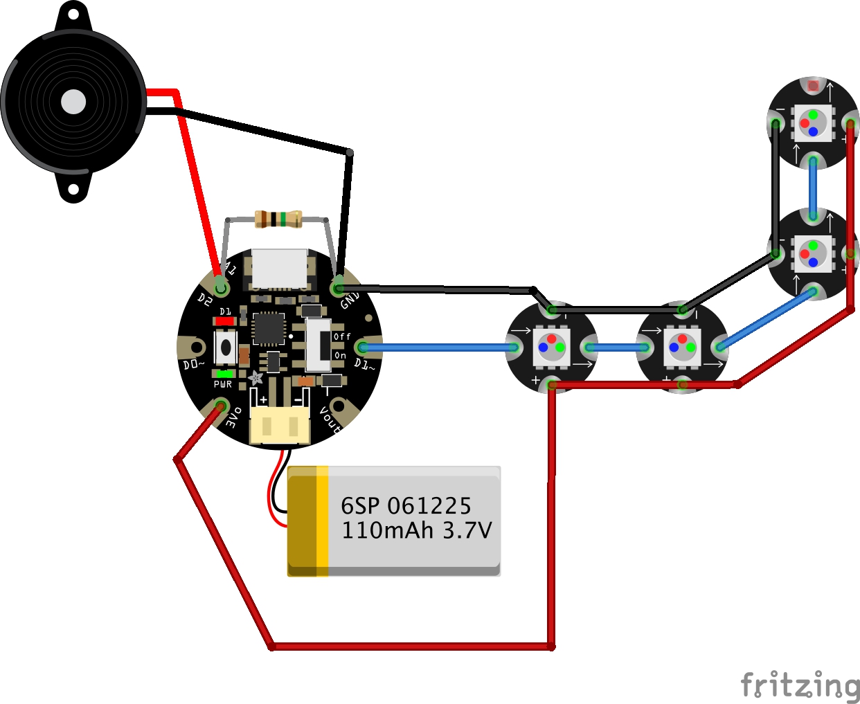
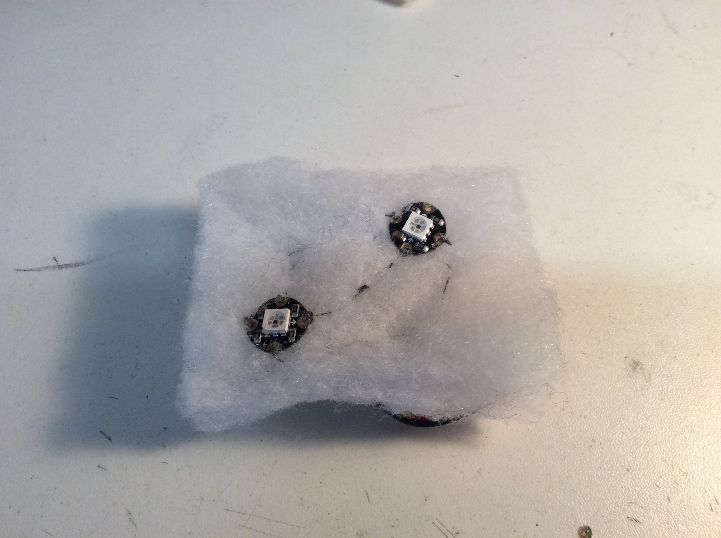
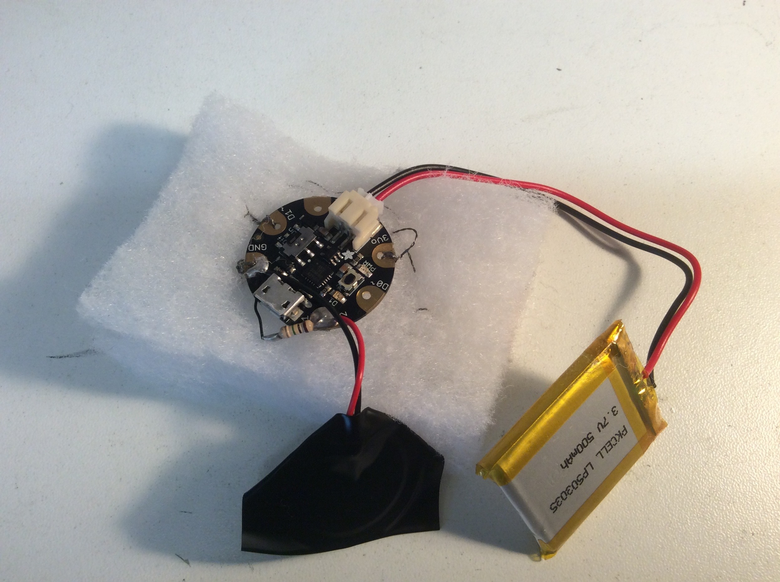
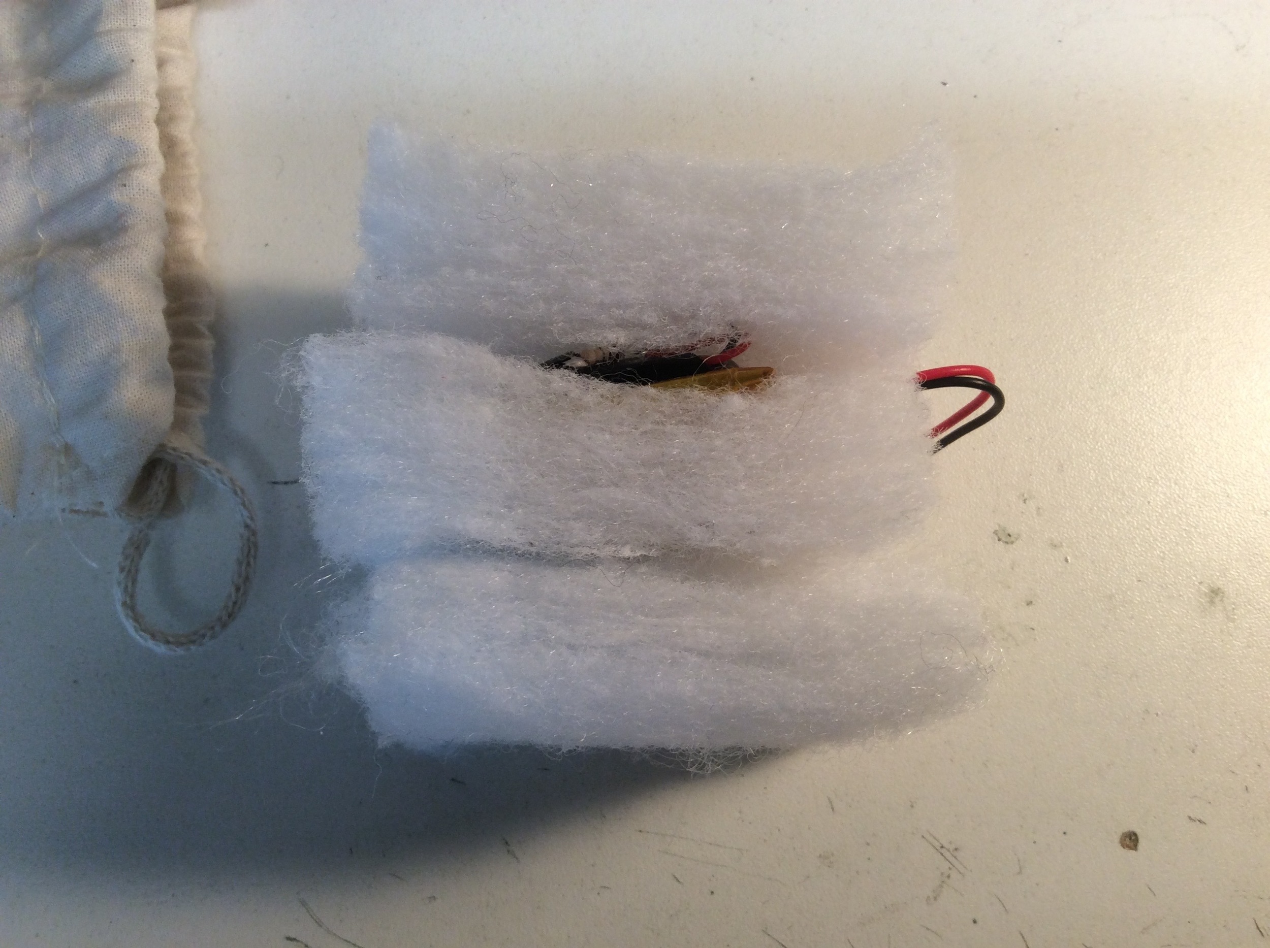
The parts were assembled between rectangles of the cushion foam with the LEDs stitched into the middle layer. The piezo element was covered in electrical tape to stop the metal touching the conductive thread (remember it is pretty much like bare wire so don't let it touch things it shouldn't!), and layered underneath the battery and Gemma board. The final assembly was then put into a little cotton bag.
I made sure to use crocodile clip test leads to check the hardware before I wired it up for real and tested each component as it was sewn in. The thread I used really needed clear nail varnish painting on the knots as soon as you have tied it off to stop them coming undone, but the one I have linked above says it is rough so ties up better. You could also stuff the bag with something smelly and maybe a vibration motor for a true multi sensory experience!
Final code:
//Luke Woodbury 4/11/15 dotLib.org
//Use Piezo as pressure sensor inside squashy foam filled bag
//to trigger colour change in LED animation
//Code based on:
// - NeoPixie Dust Bag by John Edgar Park jpixl.net
// - Adafruit GEMMA earring code and Adafruit NeoPixel buttoncycler code
// - Arduino knock sensor example


#include <Adafruit_NeoPixel.h>  //Include the NeoPixel library

#define NEO_PIN 1        // DIGITAL IO pin for NeoPixel OUTPUT from GEMMA
#define PIXEL_COUNT 4   // Number of NeoPixels connected to GEMMA
#define DELAY_MILLIS 10  // delay between blinks, smaller numbers are faster
#define DELAY_MULT 8     // Randomization multiplier on the delay speed of the effect
#define BRIGHT 100        // Brightness of the pixels, max is 255

// Parameter 1 = number of pixels in strip
// Parameter 2 = pin number on Arduino (most are valid)
// Parameter 3 = pixel type flags, add together as needed:
//   NEO_RGB     Pixels are wired for RGB bitstream (v1 FLORA pixels, not v2)
//   NEO_GRB     Pixels are wired for GRB bitstream, correct for neopixel stick (most NeoPixel products)
//   NEO_KHZ400  400 KHz bitstream (e.g. FLORA pixels)
//   NEO_KHZ800  800 KHz bitstream (e.g. High Density LED strip), correct for neopixel stick
Adafruit_NeoPixel pixels = Adafruit_NeoPixel(PIXEL_COUNT, NEO_PIN, NEO_GRB + NEO_KHZ800);

//Piezo bits
#define knockSensor 1 // the piezo is connected to analog pin 1
const int threshold = 50;  // threshold value to decide when the detected sound is a knock or not
int sensorReading = 0;      // variable to store the value read from the sensor pin

int showColor = 0;    //color mode for cycling

void setup() {
  pixels.begin();
  pixels.setBrightness(BRIGHT);
  pixels.show();                //Set all pixels to "off"

  //pinMode(knockSensor, INPUT);
}


void loop() {

  int RColor = 100; //color (0-255) values to be set by cylcing touch switch, initially GOLD
  int GColor = 0 ;
  int BColor = 0 ;

       if (showColor==0) {//Garden PINK
         RColor = 242;
         GColor = 90;
         BColor = 255;
       }
       if (showColor==1) {//Pixie GOLD
         RColor = 255;
         GColor = 222;
         BColor = 30;
       }
       if (showColor==2) {//Alchemy BLUE
         RColor = 50;
         GColor = 255;
         BColor = 255;
       }
       if (showColor==3) {//Animal ORANGE
         RColor = 255;
         GColor = 100;
         BColor = 0;
       }
       if (showColor==4) {//Tinker GREEN
         RColor = 0;
         GColor = 255;
         BColor = 40;
       }

  //sparkling
  int p = random(PIXEL_COUNT); //select a random pixel
  pixels.setPixelColor(p,RColor,GColor,BColor); //color value comes from cycling state of momentary switch
  pixels.show();
  delay(DELAY_MILLIS * random(DELAY_MULT) ); //delay value randomized to up to DELAY_MULT times longer
  pixels.setPixelColor(p, RColor/10, GColor/10, BColor/10); //set to a dimmed version of the state color
  pixels.show();
  pixels.setPixelColor(p+1, RColor/15, GColor/15, BColor/15); //set a neighbor pixel to an even dimmer value
  pixels.show();

  //piezo check
   // read the sensor and store it in the variable sensorReading:
  sensorReading = analogRead(knockSensor);

  // if the sensor reading is greater than the threshold:
  if (sensorReading >= threshold) {
      showColor++;
      if (showColor > 4)
        showColor=0;
       }
  }
Pop Up Play- Embrace Arts 3 Day Workshop
DotLib took the Pop-Up-Play system to the Embrace Arts Centre in Leicester for a three-day workshop event run by Marianne Pape. The workshop aimed to use PUP to help a small group of home-educated children, aged 7-10, interact with the art exhibition in the gallery by Mark Hamilton.
Day one was spent unleashing the system on the children. They were introduced to the separate elements but descended into creative chaos when the Kinect part of PUP was activated. They immediately began interacting with the screen. This carried on for the rest of the morning with different children exploring the different functionality of the system, at times switching roles and directing each other regarding how they were using the system. They were using the webcam alongside physical props to mix digital and physical elements. There were some great interactions of children creating a maze in the afternoon. This involved a maze being drawn and then captured by the webcam operator, a player who moved the physical piece around the maze (Mario kart or army man), and a technologist to control the PUP system on the iPad. This gave the children the chance to really explore how they were going to use the different elements available and they were very forthcoming with ideas.
Day two moved to a different room. The idea of the mazes developed further as some of the children had made new mazes overnight, and they had also bought in objects from home. We also developed some new media to be added to the PUP system, both in terms of getting crafty, and taking photos of the exhibition to put in the system, alongside photos of the children’s items from home. The children started to think about how they could get their parents involved in the process and demonstrate, not only the system to them, but also all the content that they had created. They discussed bringing all the different content and created components together to form a game whilst getting to grips with the system. One of the things that was very impressive was their ability to master moving through different scales and with different setups, to highlight different media and extend the maps that had been created.
Day three saw a move back to the main hall and a final hunkering down of roles. The children had pre-selected which area they wanted to work in and assigned jobs to each other and themselves. Who would control the webcam, who would announce things, who would do sound effects and so on. There were some rehearsals with the system and new jobs. We also loaded up all the new media for them to show their parents and incorporate into the games. The actual presentation went fantastic and the kids really owned the system and the content with very little input from us. The parents seem to really see the value in being able to contribute to the system. Whatever the preferred mode of interaction was for the child, the system provided an outlet for their creative ventures. It was a brilliant three days of straddling between the digital and physical world and exploring art and interactive lands.