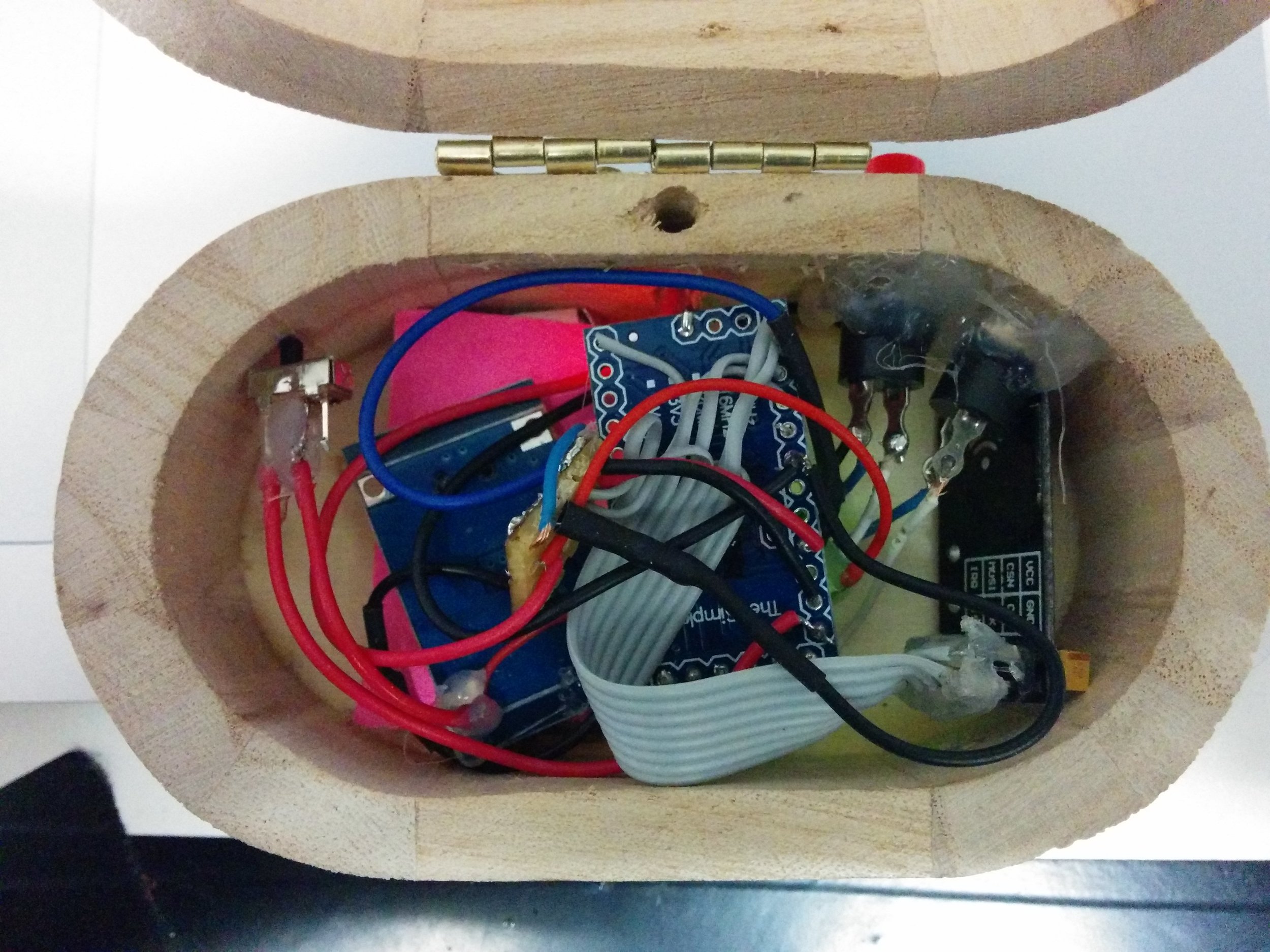
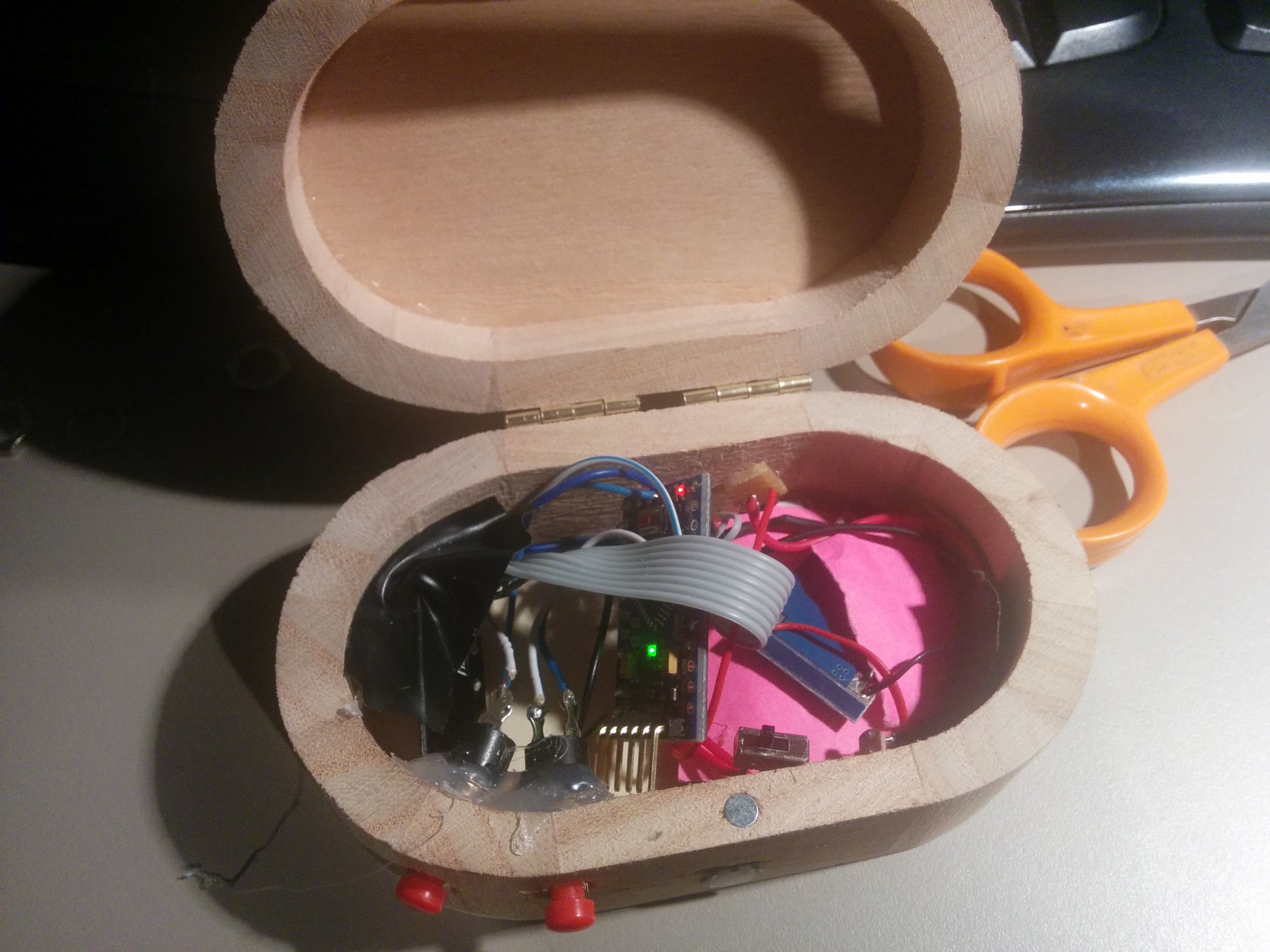
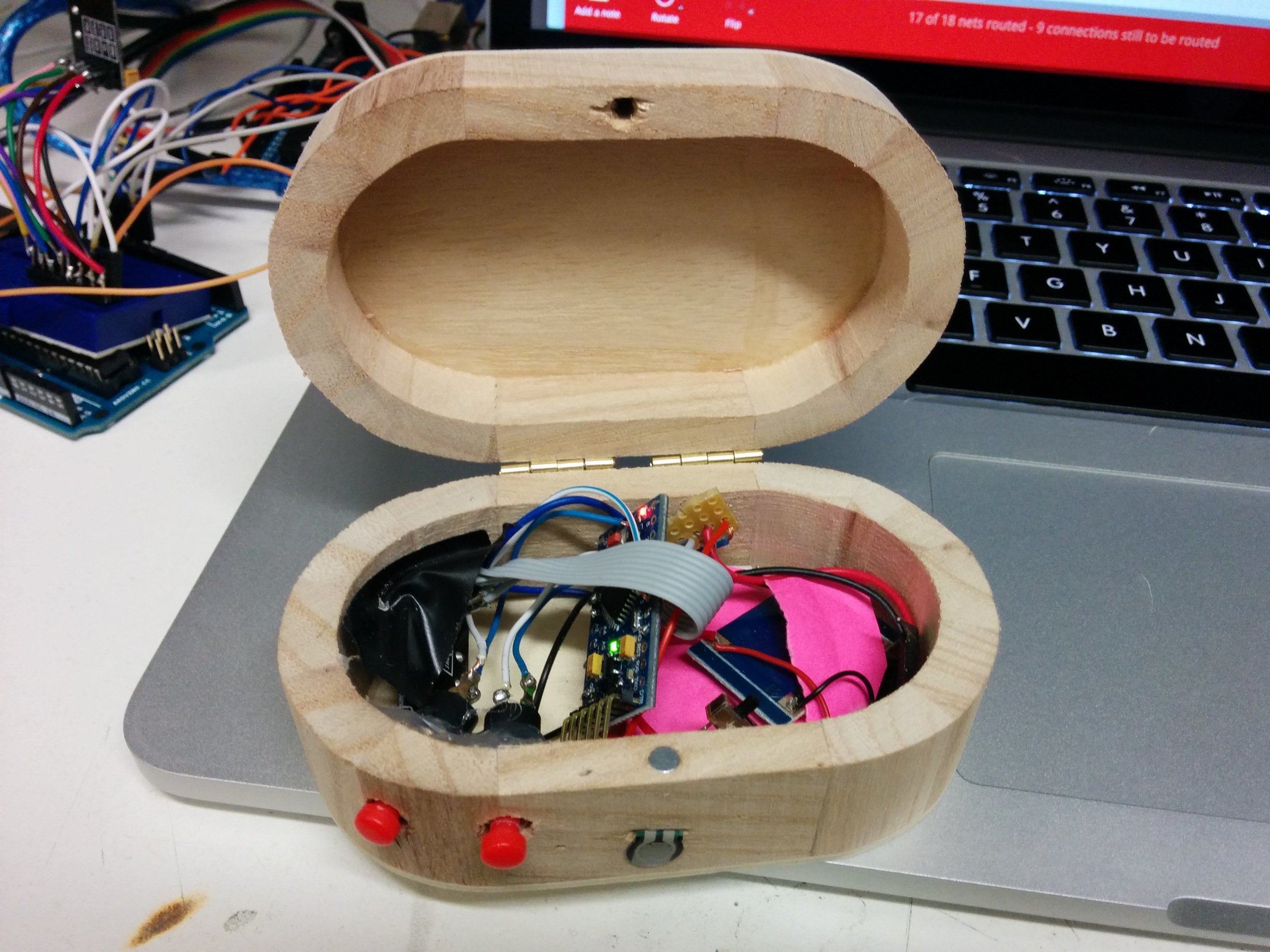
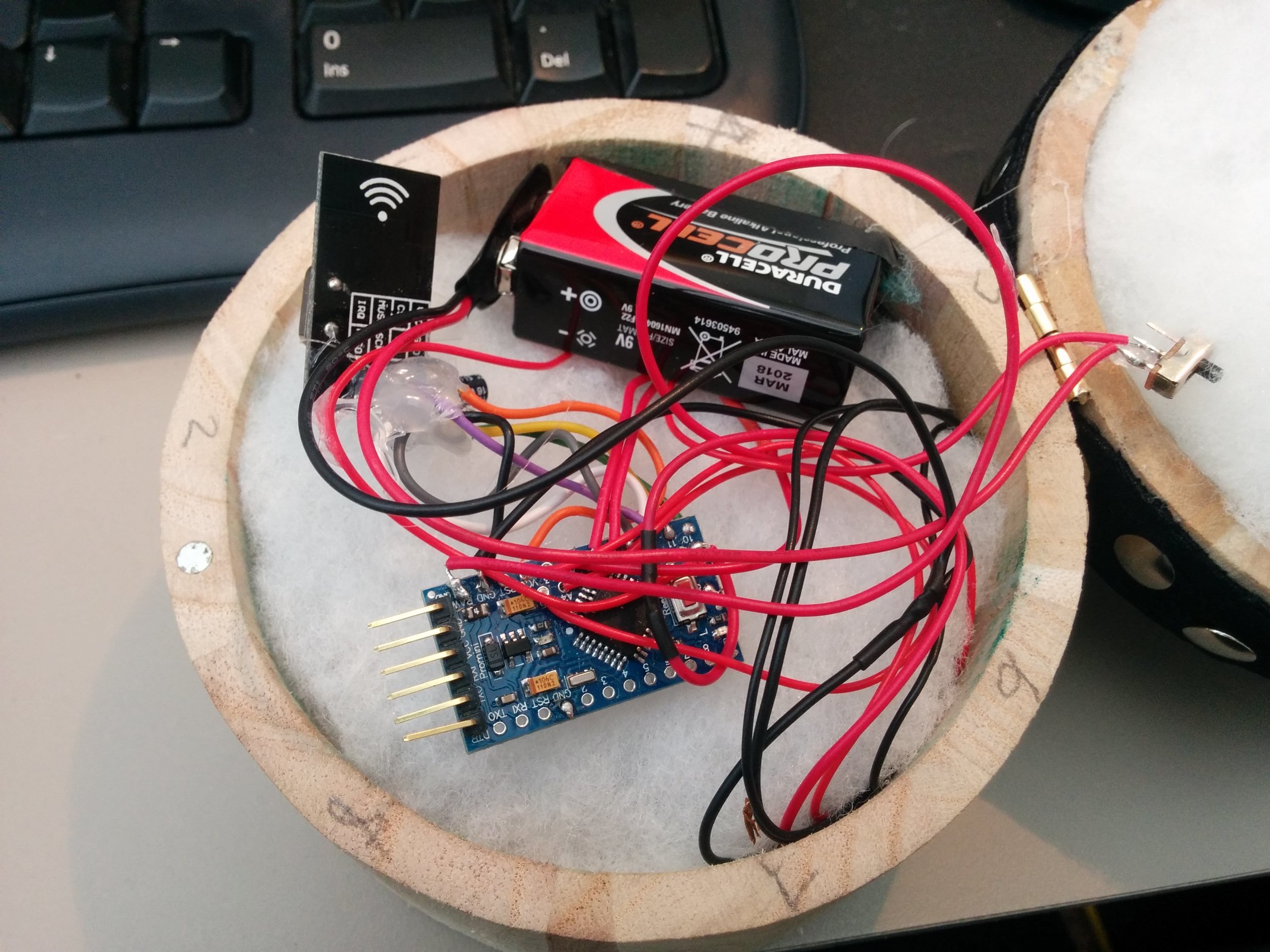
Our idea was to create a wireless filter box. I wanted to use some of the nrf240l1 radio modules I have acquired as they provide a very cheap mechanism for wireless communication, and there are lots resources available to make them work with Arduino. A detailed tutorial on using Arduino + Nrf24l01 running into Max/MSP software can be found on my website here.
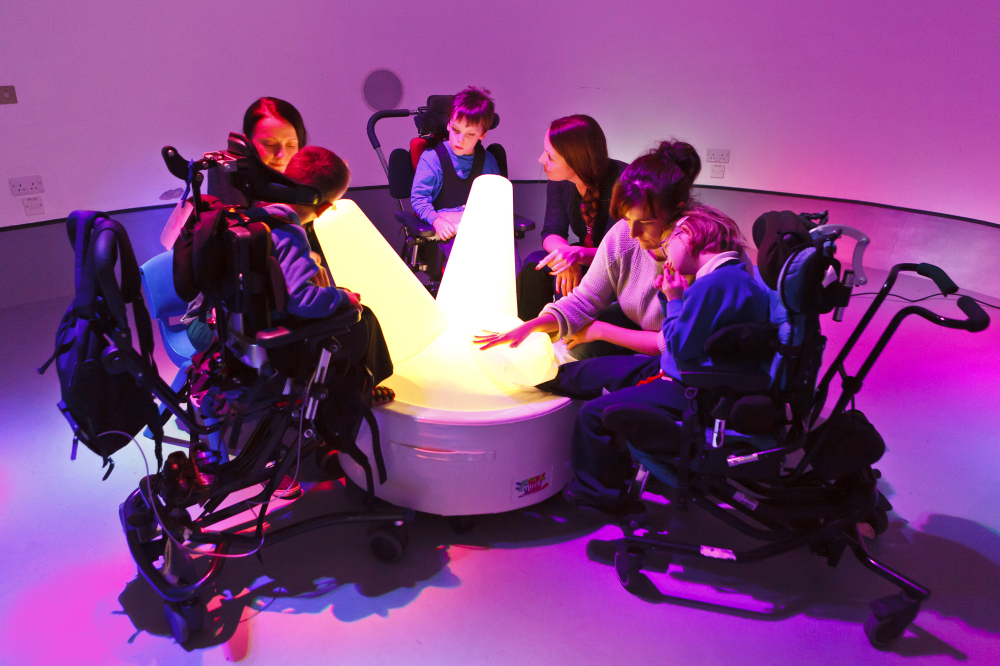
Discussing the box!
We discussed:
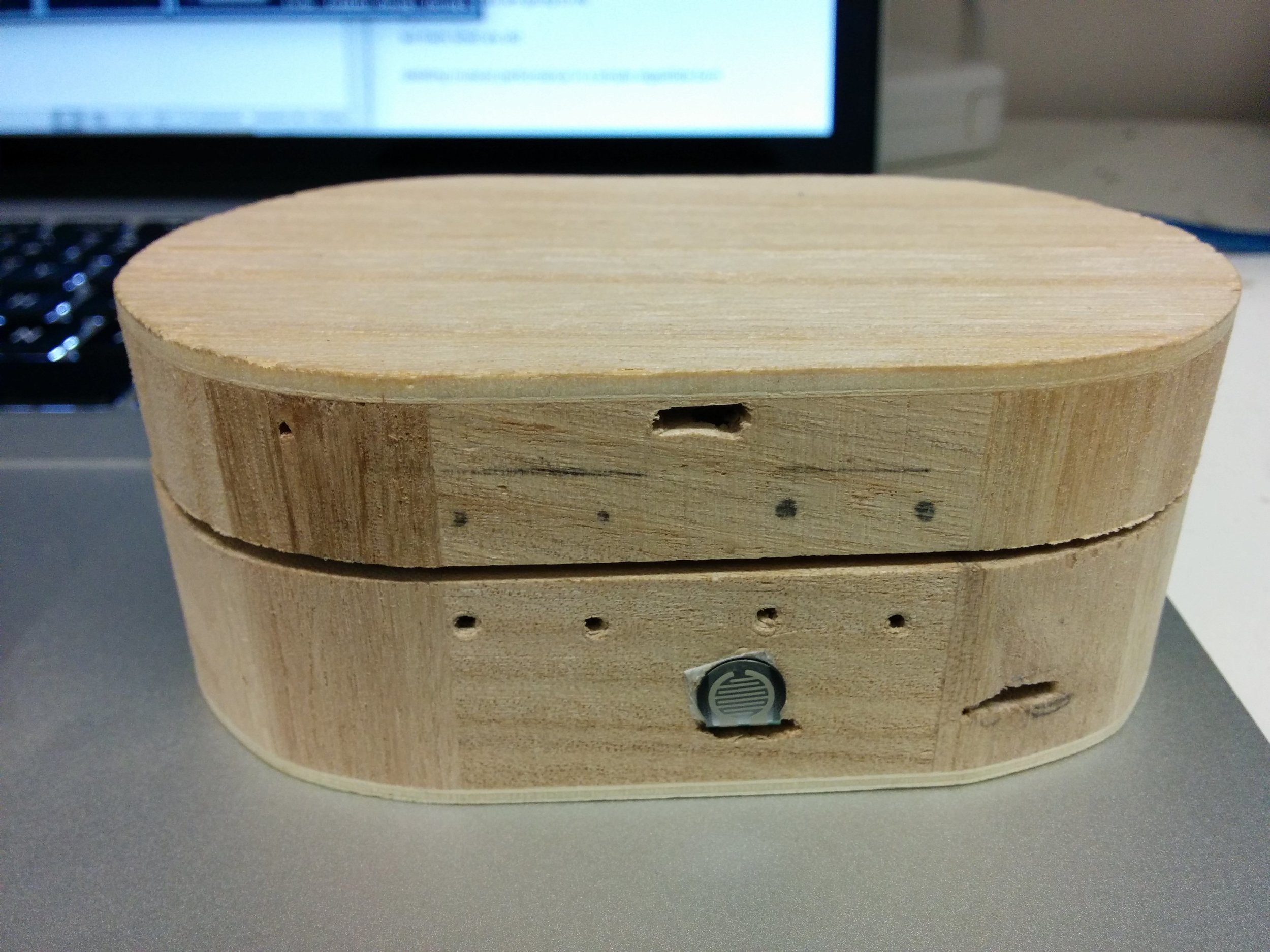
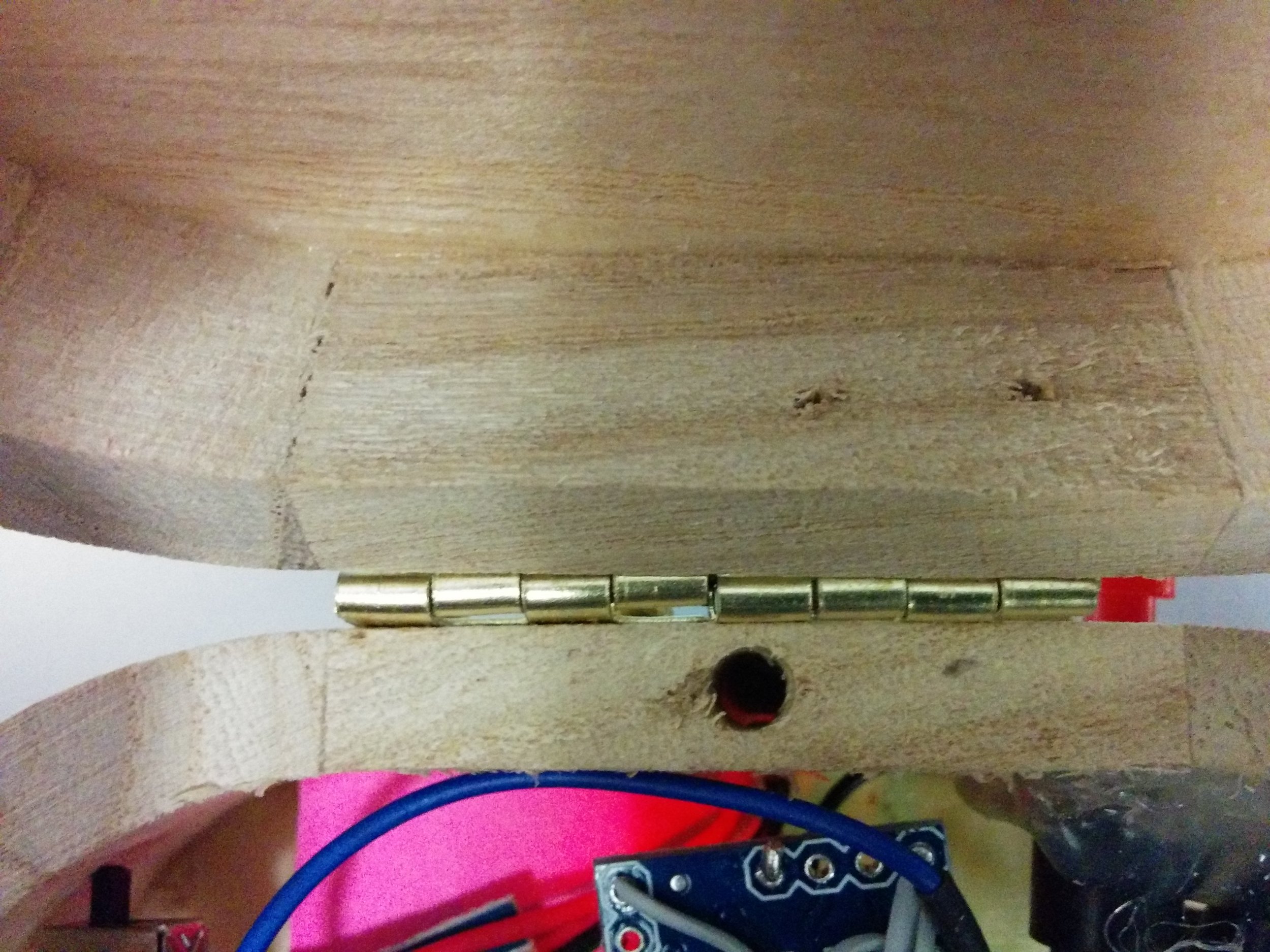
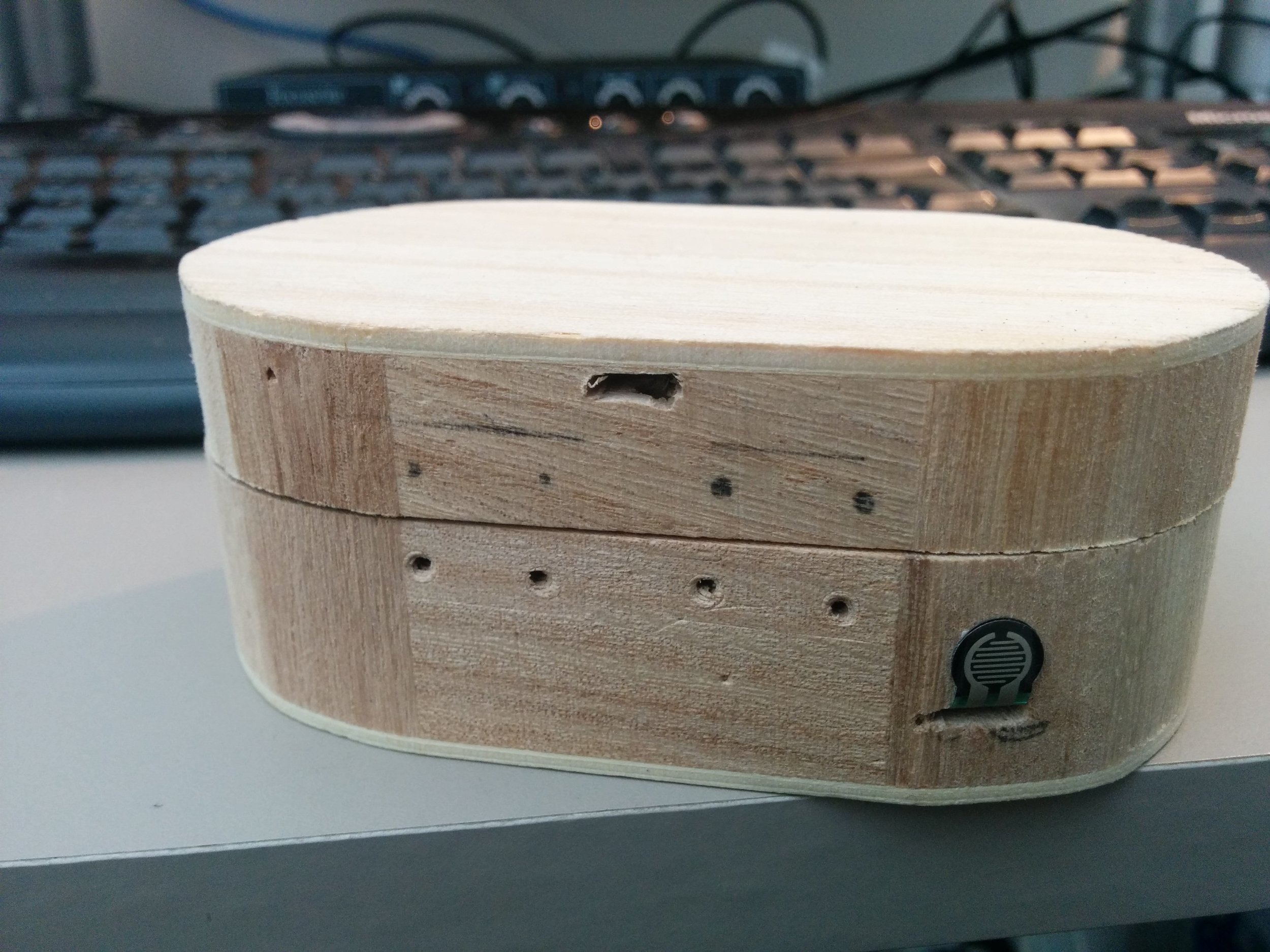
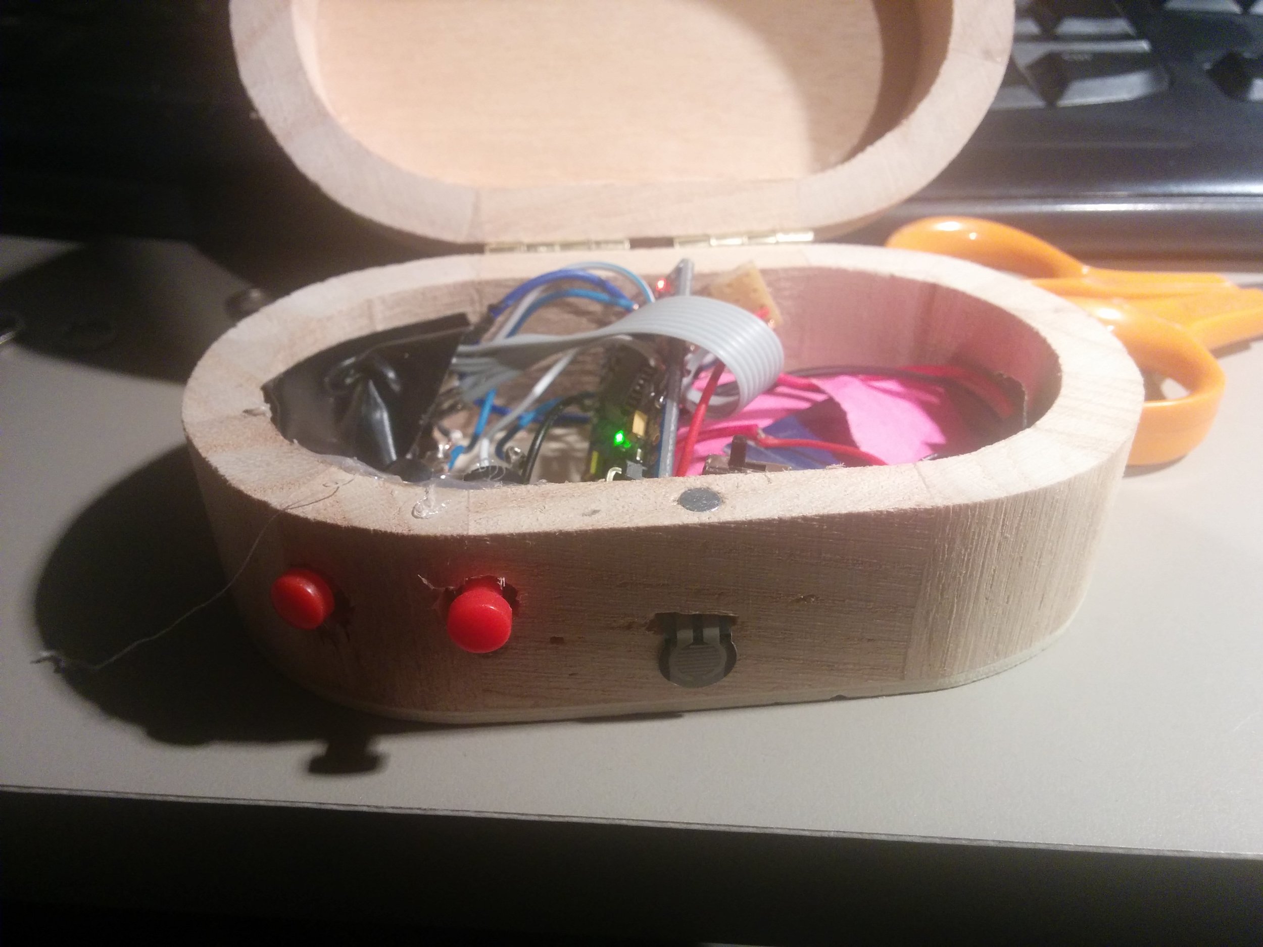
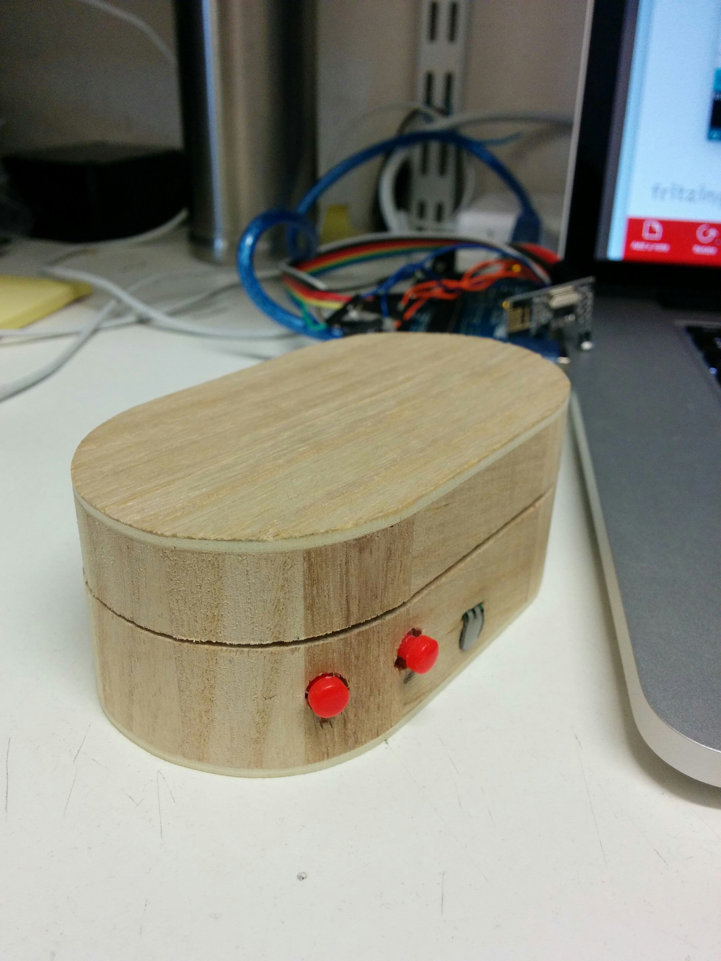
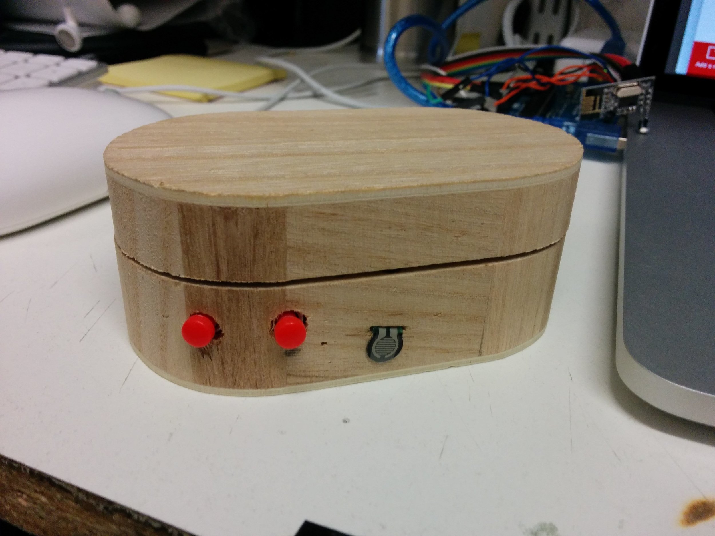
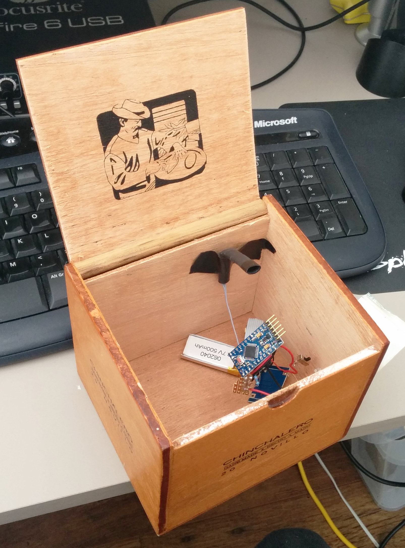
The wooden boxes I had purchased and selected a small oval shaped one as the best shape and size to fit in the hand.
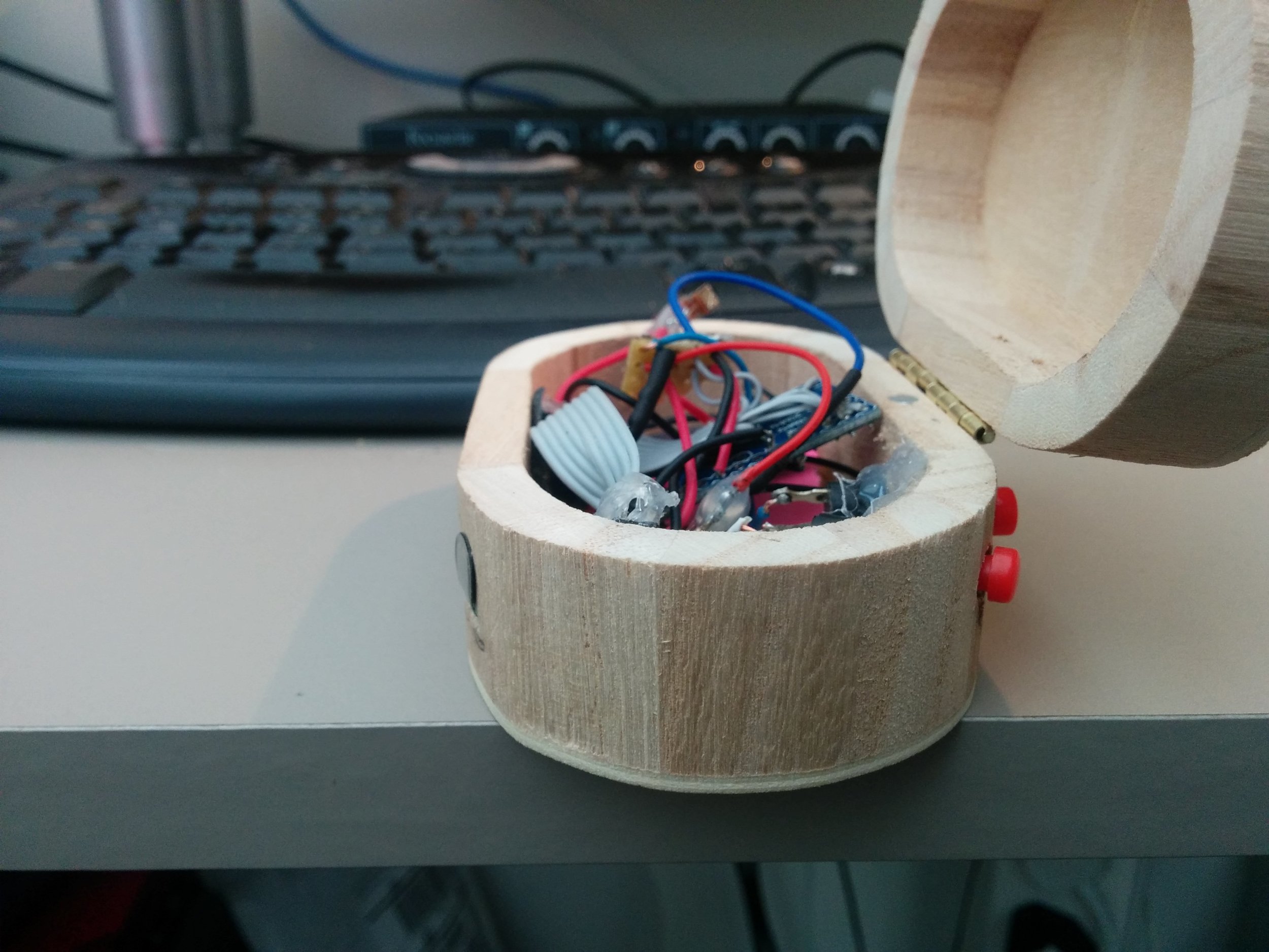
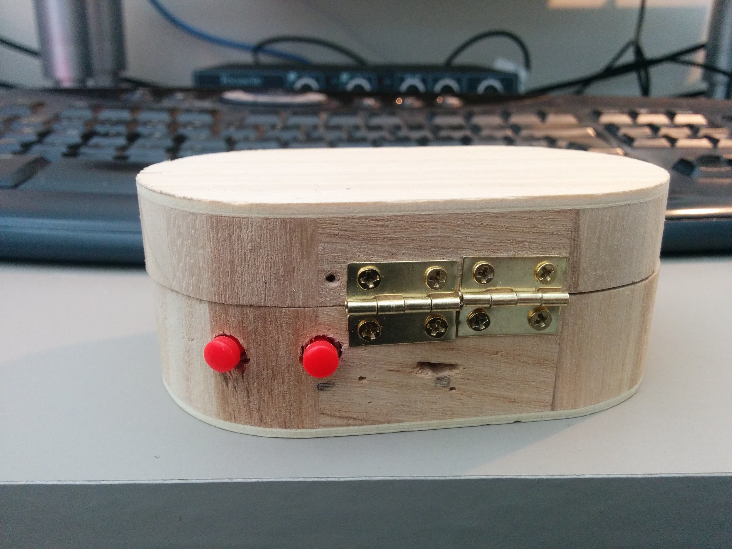
Buttons- having some (x2) to enable more functionality- options included click buttons that would provide tactile feedback when depressed or valve style that would more naturally mimic an interaction with an instrument such as a trumpet, like a valve, these would give feedback not as obviously as a click but more suited the instrument paradigm.
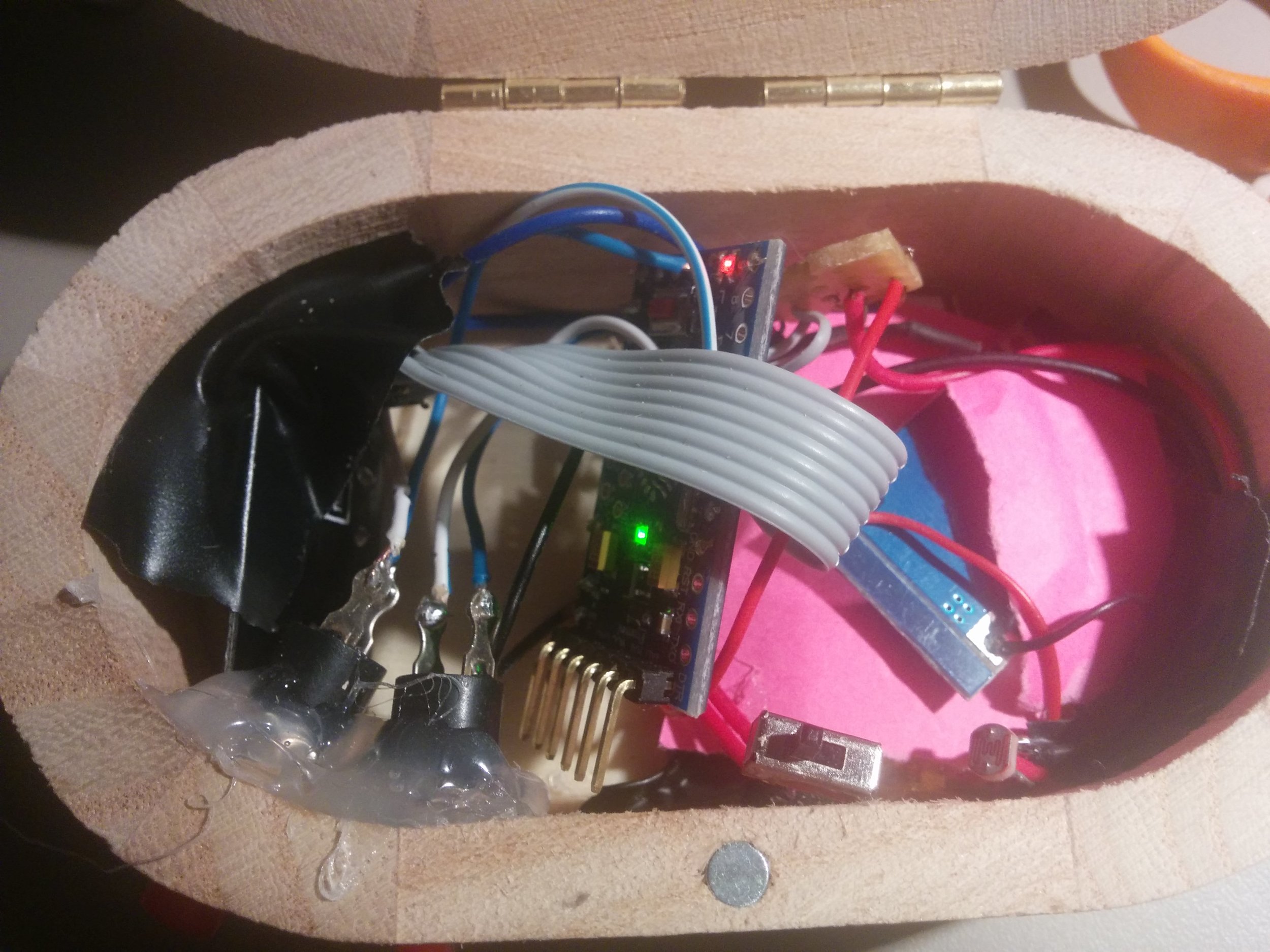
Adding a force sensitive resistor (FSR) that could then be pressed harder or softer to achieve some of the effects you would with other instruments such as when fretting a guitar, and allow expression through fingertip movement and pressure of the hand on the box. The mapping of the FSR could then be naturally connected to something like the amplitude of the sound so when pressed harder the sound would be louder, again going with what a player might naturally expect from an interaction of that style.
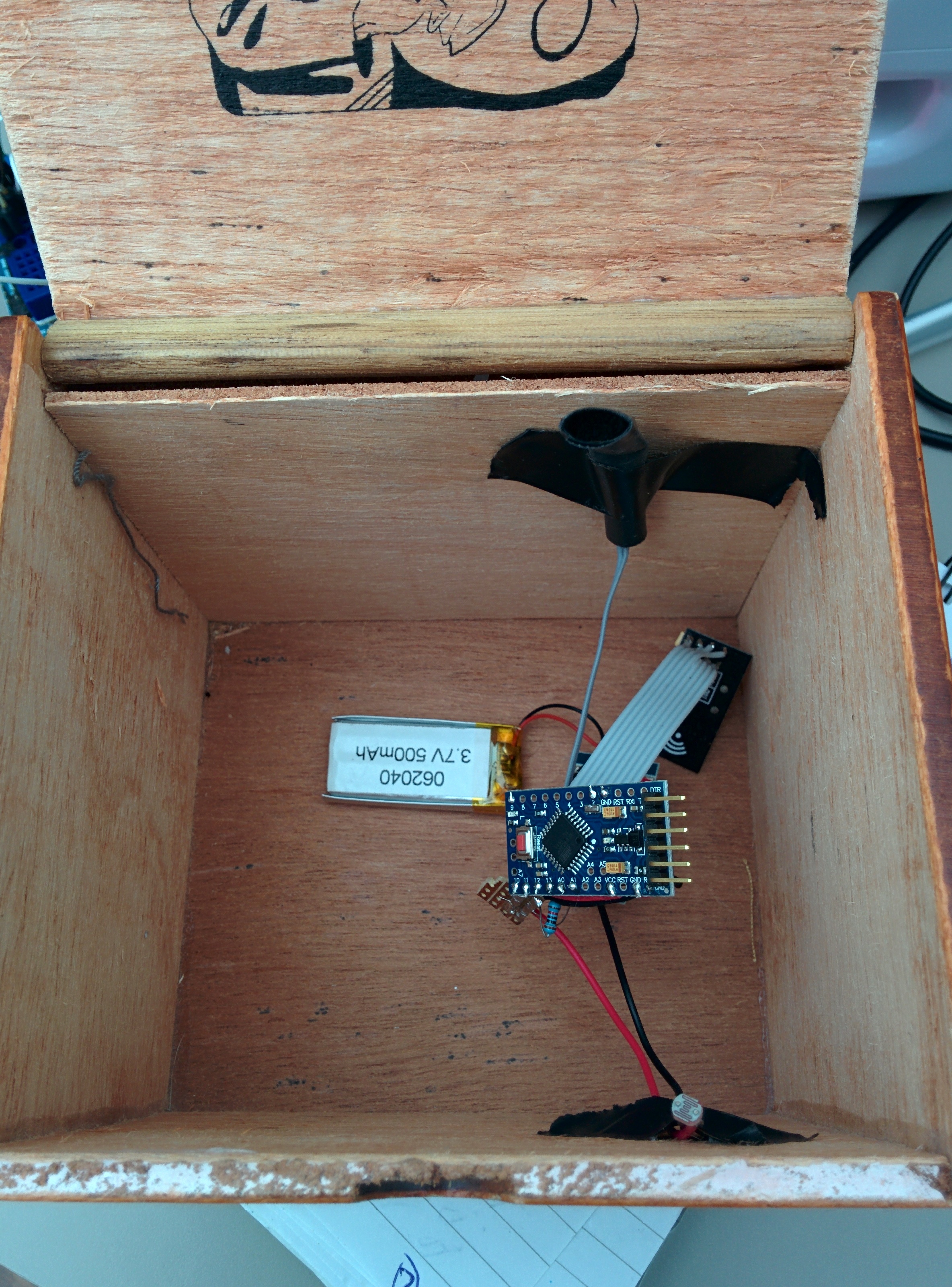
Light dependent resistor (LDR) this worked well as a mechanism to control some sort of filter, or for example the mute of a trumpet, the cutoff frequency of the sound or the volume. This is taking the movement of the opening and connecting it to any kind of parameter that might need fine movement and can be used to get effects like vibrato and tremolo. A parallel can also be drawn between something like scratching (dj style) by opening and closing the lid, and when connected to a filter controlling some element of feedback, using noise as the sound generator. We had a little play with using the light dependent resistor to control the cutoff frequency on a filter over sounds and using the motion to trigger MIDI notes but felt that the latter did not really play into the strengths of the opening and closing of the box as much as the controlling of an effect.
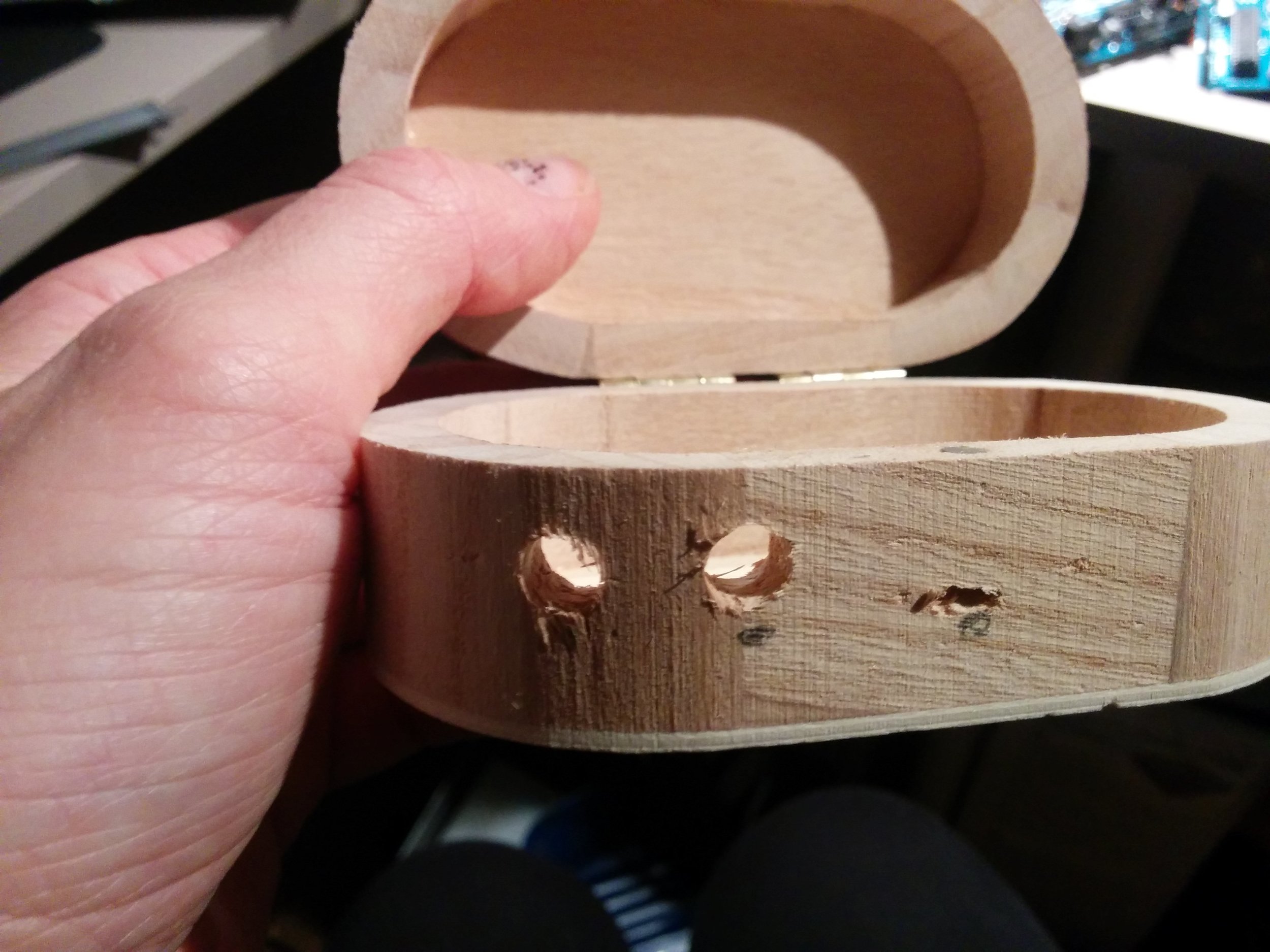
The aim with the filter box was to create something that when held in a natural position would allow access to the 2 buttons and the FSR as well as facilitating the opening and closing of the lid so that the elements could be used in conjunction with each other and separately in an ergonomic way.
The Pressure Box
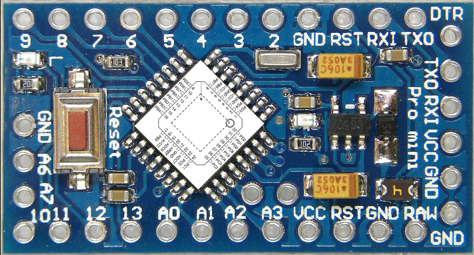
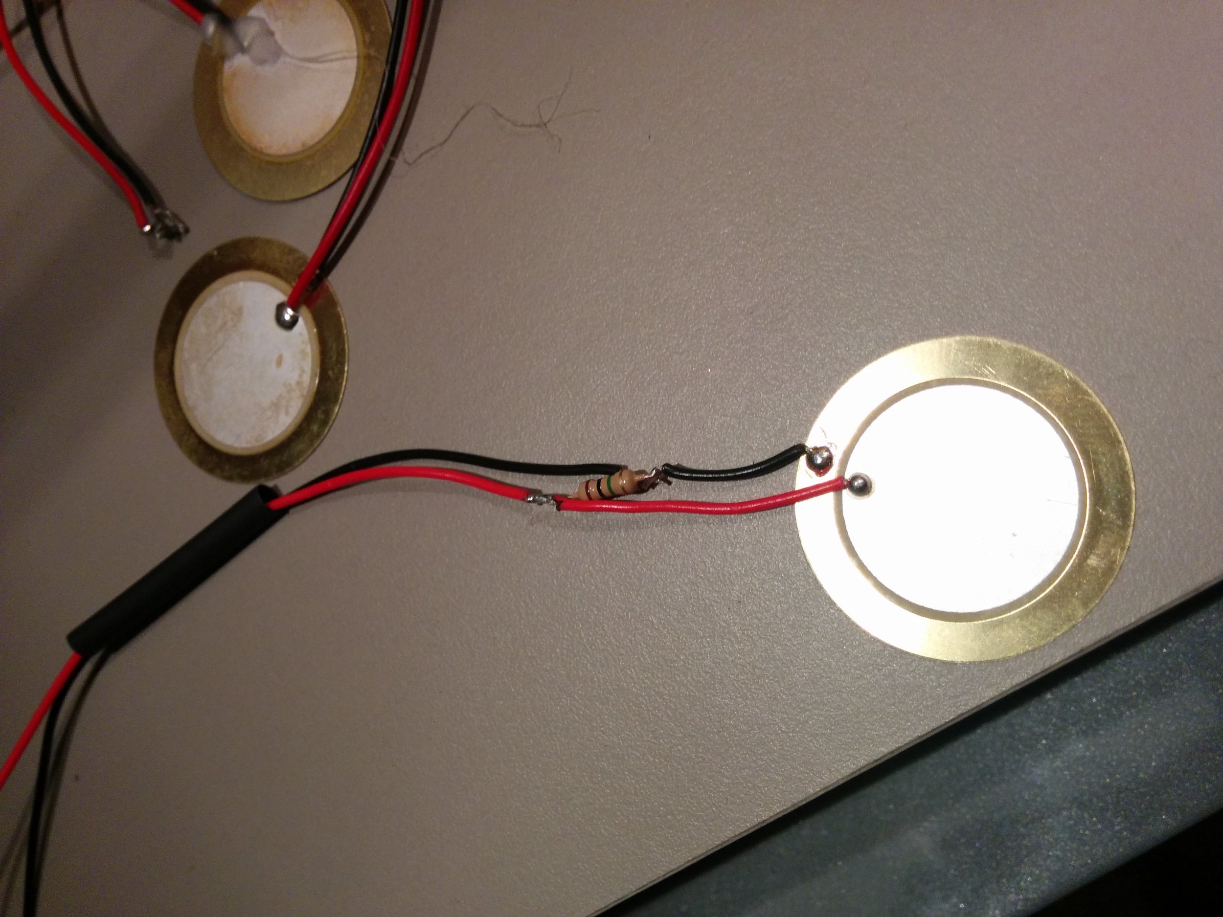
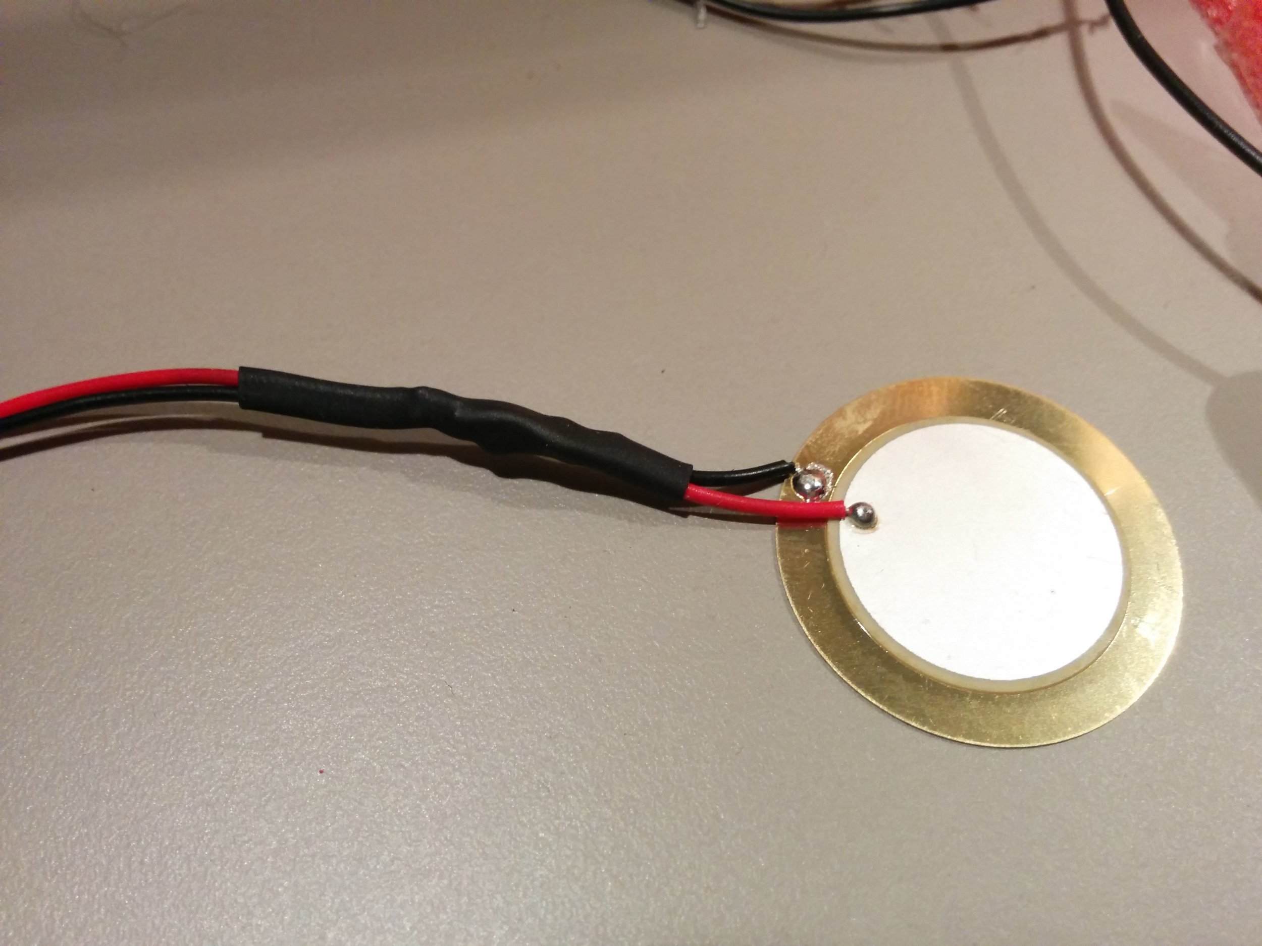
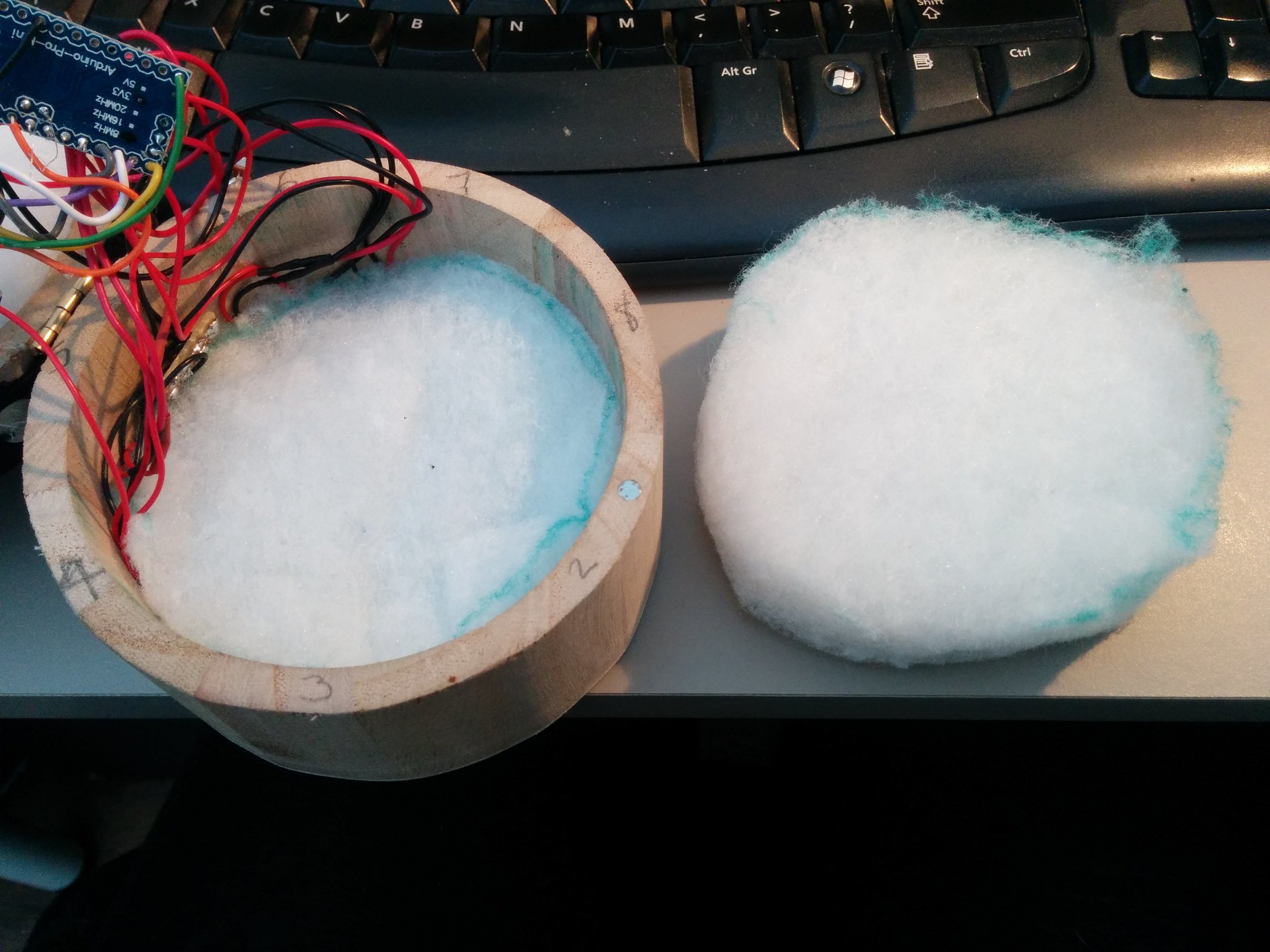
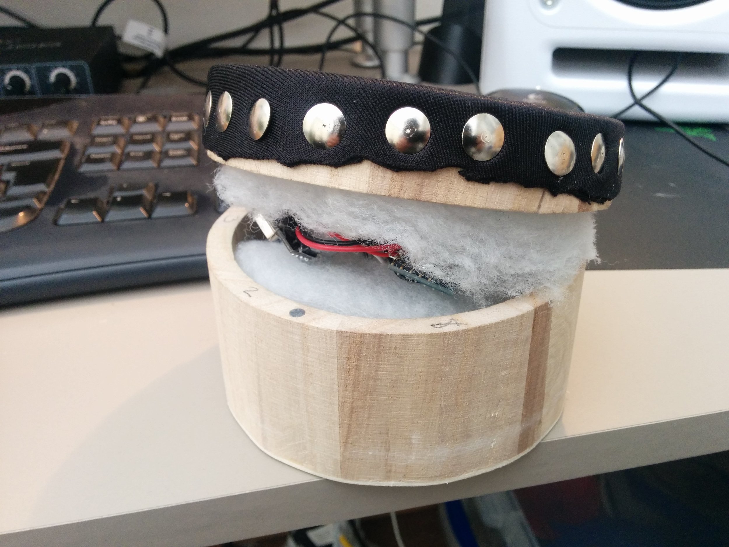
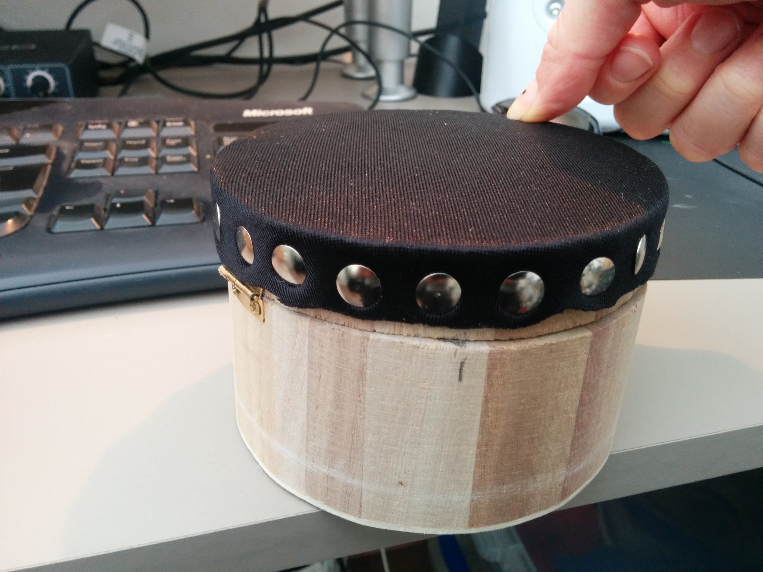
We discussed the pressure box and using an array of piezos arranged around the bottom of the circular wooden box to create 8 potential pressure points. The Arduino pro mini we are using in the instruments allows for 8 analogue inputs so would suit this set-up. The box can then be filled with foam and topped with a soft tactile yet spongy material such as neoprene, or potentially some sort of skin stretched over the top in the style of a tambourine and secured down with pins. Being that the piezos are very sensitive to vibration there may be some cross talk between the 8 units but this could provide useful for expression. The sensitivity of the piezos allows for tapping the box to trigger or modulate the sound also.
Future boxes
The hexagonal box though not used yet could potentially feature a new mode of interaction for each of its faces to allow a player to choose their preferred interaction mode and mechanism, this may be one for future exploration.
Next Steps
I will now review what we have discussed and implement them into some more prototypes!